Dismantle the automatic transmission in a place protected from dust to prevent contamination of the transmission parts
When disassembling, check the condition of the gearbox parts for wear and damage
Use only plastic hammers to separate the parts of the crankcase. Do not use rags when disassembling the gearbox: the fibers of the rag can clog the fluid channels.
Some of the parts are similar, so when disassembling, arrange them so as not to confuse them.
Remove the control valve block and clean it completely if the clutch or brake band is burnt or the quality of the fluid in the automatic transmission has deteriorated.
Before disassembly, clean the outside of the gearbox with a cleaner or solvent.
Clean the removed parts with solvent and dry with compressed air.
Clean all channels and openings with compressed air and check that there are no obstructions in them.
Wear goggles when cleaning parts with compressed air.
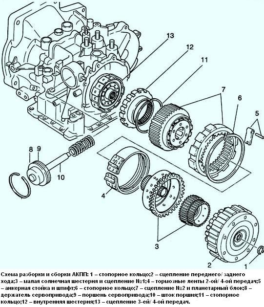
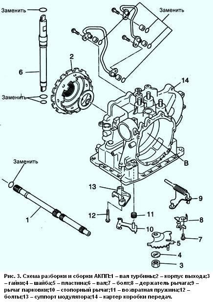
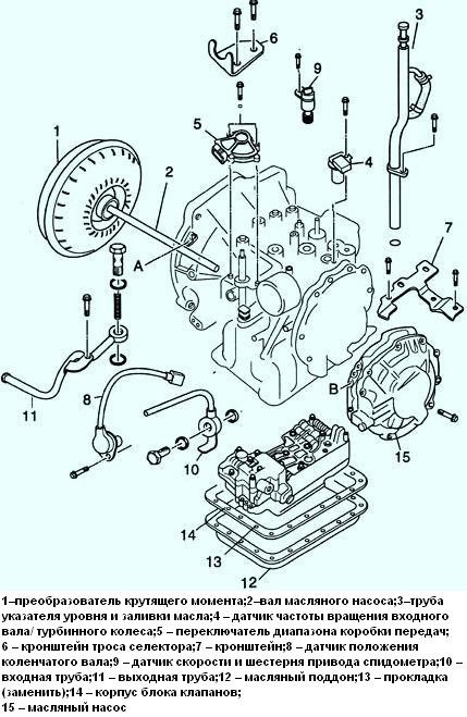
Fig. 2, 3 - Scheme of disassembly and assembly of automatic transmission
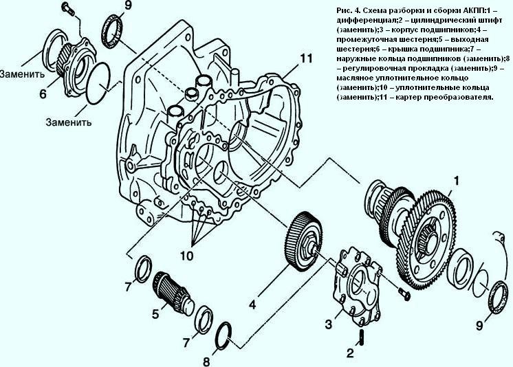
Fig. 4. Scheme of disassembly and assembly of automatic transmission
Be careful not to spill liquid when removing the torque converter.
Disassembly
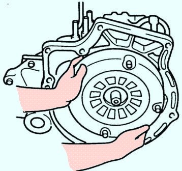
Remove the torque converter from the converter housing.
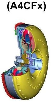
The so-called "donut" among the people. When removing, please note that the bagel is quite heavy.
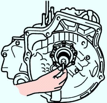
Remove the oil pump shaft by hand.
Remove the level gauge and oil fill tube.
Remove the input shaft/turbine speed sensor.
Remove the transmission range switch.
Remove the selector cable bracket.
Remove the bracket.
Remove the crankshaft position sensor.
Remove the speed sensor and the speedometer drive gear.
Remove the inlet pipe.
Remove the outlet pipe.
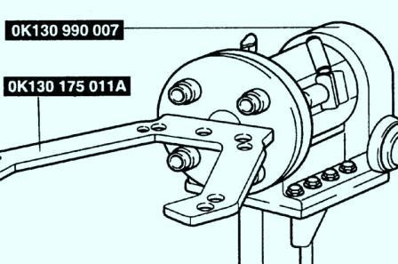
Assemble special tool OK130 990 007 with holder OK130 175 011A.
Do not tilt the gearbox to one side during disassembly as it may suddenly tip over and cause injury.
Remove the oil pan before overturning the transmission.
This ensures that all foreign matter and particles remain in the sump.
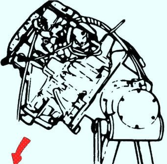
Remove the nineteen bolts and remove the oil pan
Examine any debris found in the sump and on the magnet to determine the condition of the gearbox parts.
Clutch wear particles indicate wear on the drive plate or brake bands.
Steel particles on the magnet indicate wear on the bearings, gears, or drive plate.
The presence of aluminum particles indicates wear on the bushings or gearbox housing.
If there is a large amount of foreign matter and particles, replace the torque converter and carefully check the condition of the gearbox parts.
Remove the clip (one bolt).
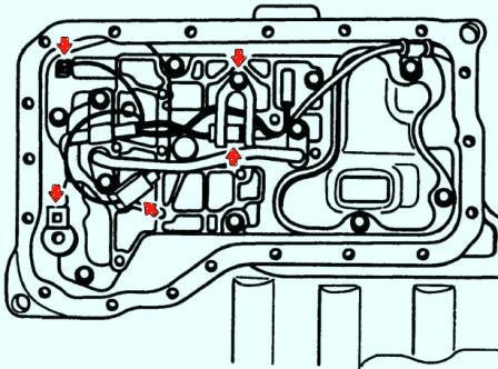
Disconnect the solenoid valves.
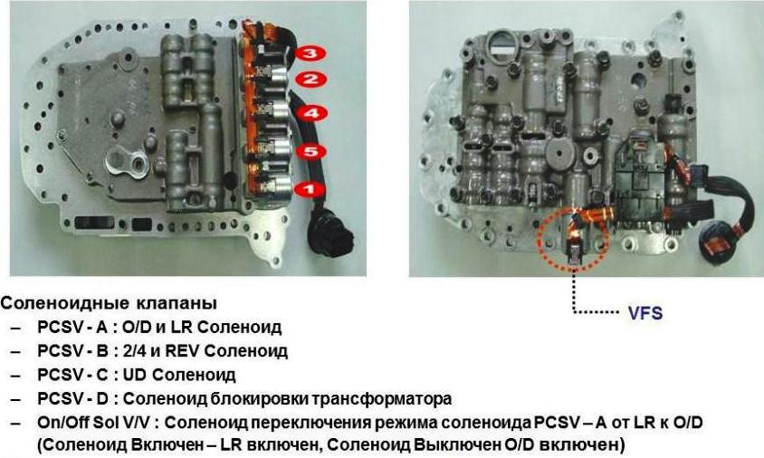
Remove the three bolts and remove the strainer.
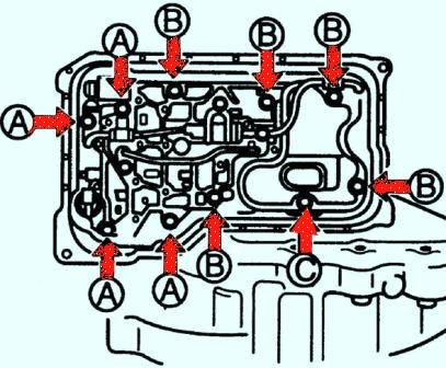
Remove screws A, B and C and remove the brackets shown in the picture.
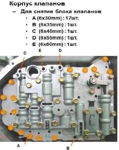
Bolt length (measured from the base of the head): A: 30mm B: 50mm C: 14mm
Remove the control valve body.
Remove the shaft and plate:
- - loosen the nuts and pull out the shaft;
- - unscrew the nuts, remove the washer and plate.
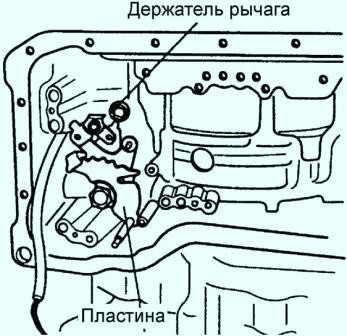
Remove the bolt and remove the parking lever holder
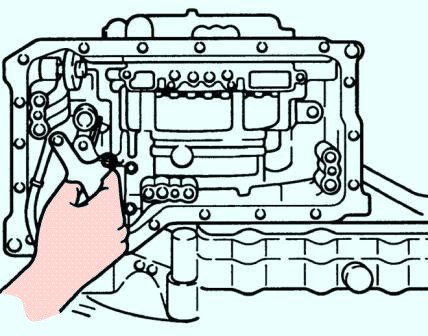
Remove the two parking lever holder bolts.
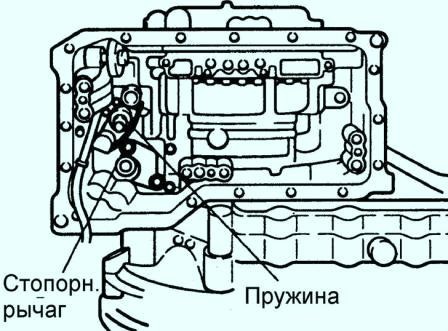
Remove the stop lever and return spring.
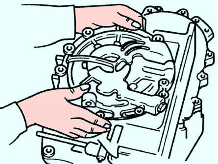
Remove the modulator support.
Remove ten bolts and remove the oil pump.
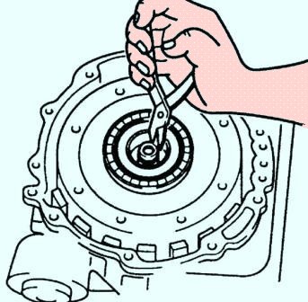
Remove the forward/reverse clutch:
- - remove the circlip of the turbine wheel shaft;
- - Lift the forward/reverse clutch assembly and remove it from the transmission.
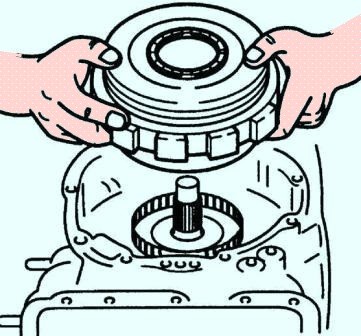
Remove the small sun gear and #1 clutch.
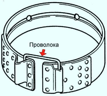
Remove brake bands 2-4.
Use a piece of wire to secure the brake band so that it is not damaged when pulled.
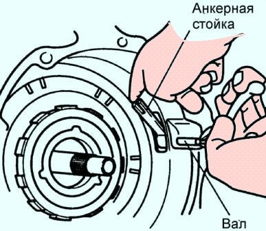
Remove the pin while supporting the anchor post.
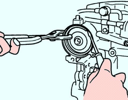
Remove the anchor post.
Remove the servo:
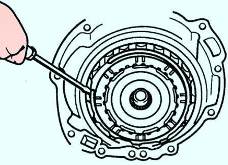
- - Squeeze the servo piston and remove the retaining ring
- - remove the servo holder, piston and spring
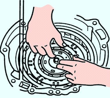
Remove one way clutch #2 and planetary assembly:
- - remove the retaining ring;
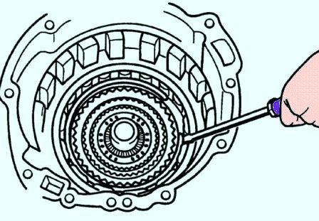
- - remove one-way clutch No. 2 together with the planetary assembly;
- - remove the friction plate.
Remove the inner gear:
- - remove the retaining ring;
- - remove the inner gear from the housing.
Remove clutch block 3-4:
- - remove the O-ring from the turbine shaft on the side of the converter;
- - pull out the turbine shaft to remove the clutch block 3-4;
- - remove the clutch block 3-4 from the turbine shaft.
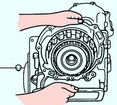
Remove the bolts (on the converter side, eight bolts and on the gearbox housing side, seven bolts) and remove the gearbox housing by hitting it with a plastic hammer.
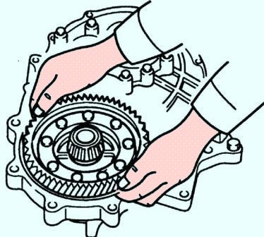
Remove the output housing from the output gear.
Remove the differential.

Remove the bearing housing:
- - use a hammer and a round punch to knock out a cylindrical pin;
- - unscrew the eleven bolts securing the bearing housing;
- - remove the bearing housing by hitting it with a plastic hammer.
Remove the idler gear assembly and output gear assembly by knocking them out from the side of the torque converter.
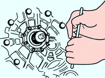
Remove the bearing cover:
- - unscrew the boltssealing bearing caps;
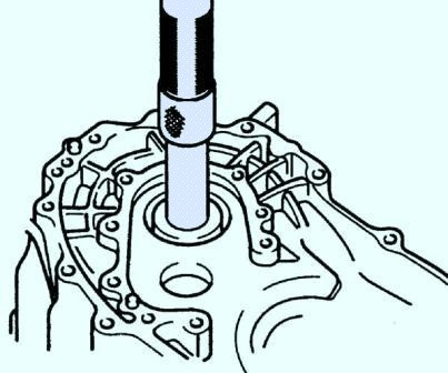
- - remove the transducer housing with the OK130 175 011A special tool;
- - Press the bearing cover out of the converter housing.
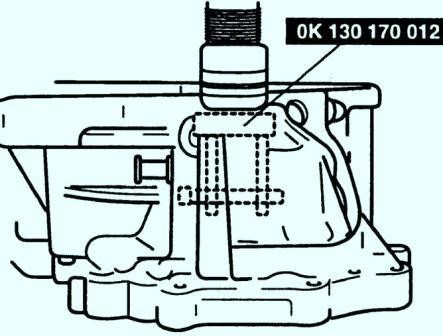
Install the previously removed bearing outer race during reassembly to adjust the bearing preload.
Remove the bearing outer ring using OK130 170 012 tool


