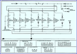
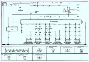
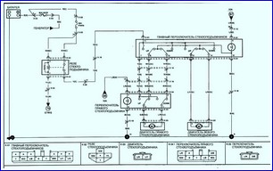
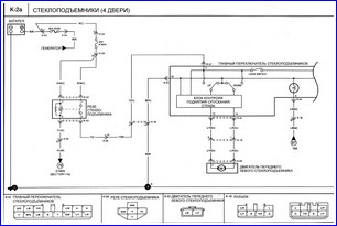
The negative ground electrical system has an operating voltage of 12 volts
Power for the electrical system comes from a lead-acid battery that is charged by a generator
It should be noted that when working with any element of the electrical equipment of the car, the wire of the negative terminal of the battery must be disconnected to prevent a short circuit and / or fire.
At regular intervals, check the location and fastening of the wires, make sure that the wires do not fray against other elements.
If you find that any wires are rubbing against other elements, move the wires aside and secure them so that this does not happen again.
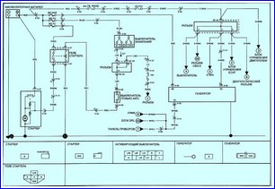
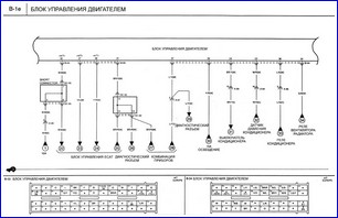
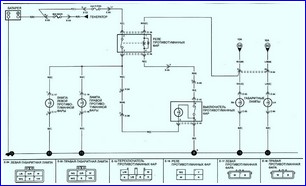
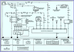
Scheme of the starting and charging system
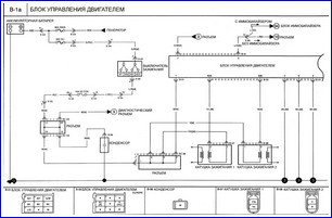
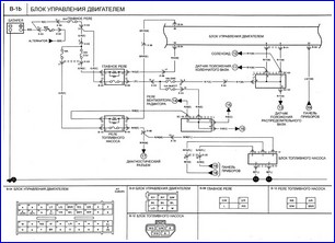
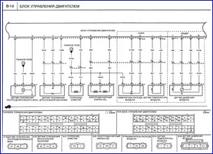
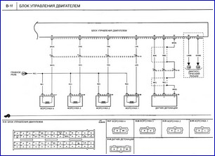
Engine control unit
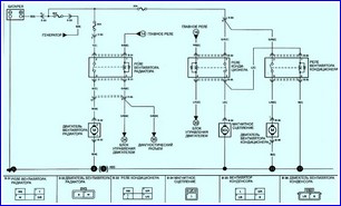
Cooling system diagram
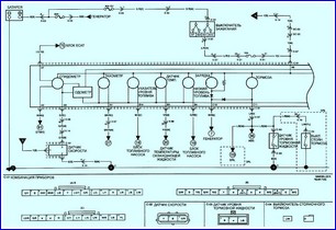
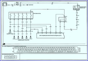
Instrument cluster and pilot lamps
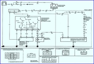
Wipers and washers
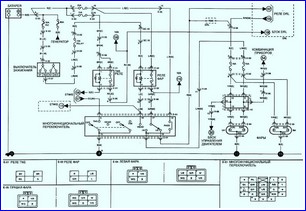
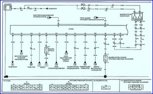
Front lighting (with airbag)
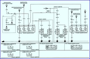
Backlight
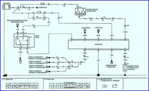
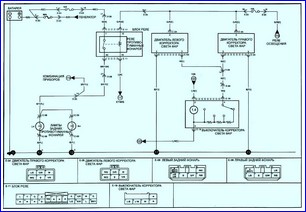
Headlights (DRL)
Front fog lights
Rear fog lights, headlight range control (HLLD)
It is forbidden to change the polarity of the power supply of various devices and devices of electrical equipment in order to avoid failure of semiconductor devices.
Never disconnect or connect the battery, gauges, or any wires while the engine is running.
It is forbidden to check the serviceability of the generator by shorting the power output to ground.
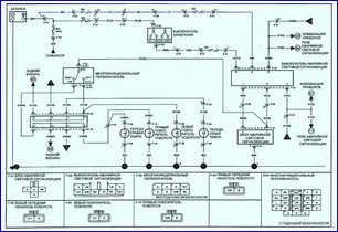
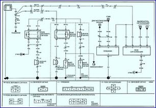
Sound signal and emergency light signaling unit
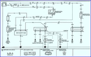
Reverse and brake lights
Air conditioning system
Electric Engagement Indicator System (ECAT)
ETWIS
Receiver, alarm relay and horn.
Illumination lamps
Radio connection diagram
Window regulators (2 doors)
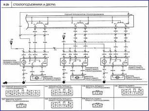
Window regulators (4 doors)
A conventional electrical circuit consists of electrical equipment, switches, relays, motors, fuses, fuses and wires and connectors that connect all the elementss between themselves, the battery and the "mass" of the car.
The cause of a malfunction can be found much faster if you determine which of the elements of this circuit are working properly.
If several components or circuits fail at once, the problem is probably a blown fuse or poor grounding, as often one fuse protects several circuits.
Electrical system performance problems are usually caused by simple causes, such as oxidized or loose contacts, a blown fuse, a blown fuse, or a faulty relay.
Visually inspect the condition of all fuses, wires, and connectors in the faulty circuit before checking other elements of the circuit.
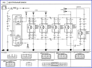
Central lock
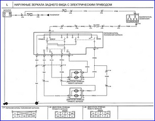
Electrically operated exterior mirrors
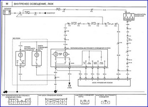
Interior lighting, sunroof
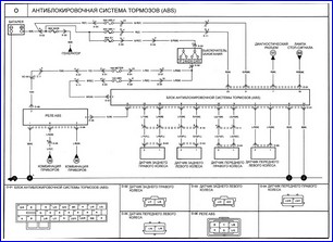
Anti-Lock Braking System (ABS)
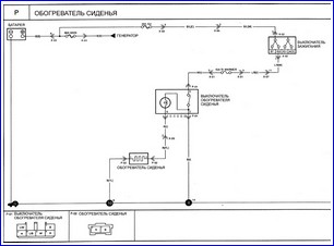
Seat heater
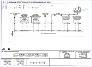
Airbags (Without side airbags)
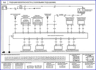
Airbags (With side airbags)
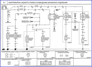
Rear window defogger and luggage compartment lighting
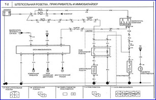
Power outlet, cigarette lighter and immobilizer
Diagnostic connector, OBD-II test connector
The main instruments needed to detect a fault in a circuit are:
- - tester or voltmeter (or 12 V light bulb with connecting wires);
- - a control light with a power source (or a device for checking the continuity of circuits);
- – ohmmeter (for measuring resistance);
- - battery;
- - probes with wires;
- - loop wire, preferably with a circuit breaker or and a fuse that can be used to test wires or electrical equipment.
To detect a loose connection or a short circuit (usually due to a bad or dirty connection or damaged insulation), the wires can be shaken by hand to see if the circuit breaks when the wire is moved.
In this way, you can find a point with an unreliable connector or a point where a short circuit occurs.
In addition to the problems associated with an unreliable connection, an electrical circuit can have two other main malfunctions - an open circuit or a short circuit.
An open in the circuit can be caused by a broken wire or a loose connection in the circuit, preventing the current from flowing.
An open in the circuit will cause the failure of any element of electrical equipment in operation, but will not blow the fuse protecting this circuit.
Short circuit faults are caused by a short in a circuit, which causes the current flowing in the circuit to flow in another circuit, most often to ground.
A short circuit is usually caused by a broken insulation that allows the power wire to touch either another wire or a grounded item such as a body.
A short circuit will blow the fuse protecting the corresponding circuit.
Before troubleshooting or repairing an electrical system, be aware that different types of wires have different colors.
To detect an open circuit, connect one of the test light probes to the negative battery terminal or vehicle ground.
Connect the second probe to the connection in the circuit under test, preferably as close as possible to the battery or fuse.
Apply voltage to the circuit. Keep in mind that in some circuits, voltage is only applied when the key in the ignition switch is turned to a certain position.
If voltage is present (which will be indicated by a lit test light or voltmeter reading), this means that the part of the circuit between the connection and the battery is good.
Continue testing the rest of the circuit in the same way.
When a point where voltage is absent is found, it means that the source of the fault lies between this point and the previous point where voltage was present. Most problems are caused by a bad connection.
The negative battery terminal is connected to the vehicle's ground—the metal of the engine/gearbox and the vehicle body—and most electrical systems are designed to have only one lead to a piece of equipment, with current returning through the metal of the vehicle's body.
This means that the attachment of the electrical equipment element and the car body are part of the electrical circuit.
Therefore, a poor or oxidized fastening can cause a large number of problems in the electrical equipment system, from complete circuit failure to unreliable circuit operation.
In particular, light bulbs may be dim (especially if another circuit using the same ground point is turned on), motors (such as wiper motors or a radiator fan) may run slowly, and turning on one circuit may affect the operation of another circuit. .
Note that many vehicles use bonding ground strips between various parts of the vehicle, such as between the engine/transmission and the body, i.e. usually when there is no metal contact between the elements due to the use of rubber fasteners, etc.
To check the reliability of the ground, disconnect the battery and connect one of the ohmmeter probes to the car's ground.
Connect the second probe to the wire or ground point you want to test.
The resistance recorded by the ohmmeter must be zero: otherwise, check the connection as follows.
If you think the connection is not good, disassemble the connection and clean to bare metal the contact surface and the wire terminal or the surface of the grounding element.
Remove completely the dirt and corrosion, then use a knife to remove a layer of paint in order to obtain a reliable metal-to-metal bond.
Fix the joint securely when assembling; when installing the wire terminal, use toothed washers between the terminal and the body.
After connecting, apply a layer of Vaseline or silicone grease to the connection to prevent corrosion.
