ABS control unit KIA RIO
The ABS control unit performs the following functions:
- - controls ABS;
- - calculates the speed of the car;
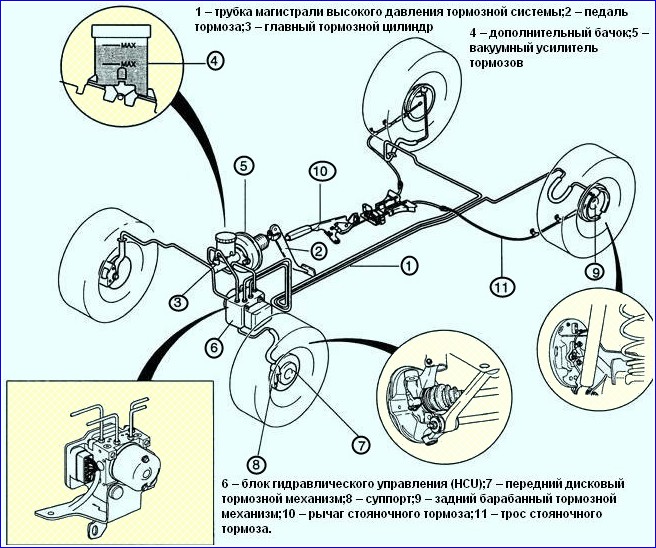
- – performs system self-diagnostics: fault codes with self-diagnosis and safety functions are stored in memory by two separate microprocessors.
Anti-Lock Braking System (ABS) includes EBD brake force distribution, ESP (if equipped), and a self-diagnostic system that detects malfunctions of system components.
ABS is used to regulate the pressure in the brake mechanisms of all wheels when braking in difficult road conditions and thereby prevents the wheels from blocking.
The ABS system provides the following benefits:
- – avoiding obstacles with a higher degree of safety, including during emergency braking;
- – reduction of the braking distance during emergency braking while maintaining roadholding and controllability of the car, including when cornering.
In the event of a system failure, diagnostics and maintenance functions are provided in case of system failures.
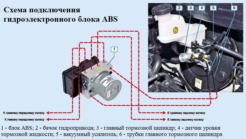
The hydroelectronic control module receives information about the vehicle speed, direction of travel and road conditions from the wheel speed sensors and the throttle position sensor.
After the ignition is turned on, the control unit energizes the wheel speed sensors, which use the Hall effect, they generate an output signal in the form of rectangular pulses. The signal changes in proportion to the rotational speed of the encoder's pulse ring.
Based on this information, the control unit determines the optimal wheel braking mode.
The following modes of operation of the anti-lock braking system are distinguished:
- – normal braking mode.
During normal braking, the intake valve is open and the exhaust valve is closed.
When you press the brake pedal, brake fluid under pressure is supplied to the working cylinder and actuates the wheel brakes.
When the brake pedal is released, the brake fluid returns to the brake master cylinder through the intake and check valves;
- – emergency braking mode.
If the wheel locks up during emergency braking, the module issues a command to the pump motor to reduce the supply of brake fluid, then voltage is applied to each solenoid valve.
The intake valve closes and the brake fluid supply from the master cylinder and pump is shut off; the exhaust valve opens, and the brake fluid flows from the working cylinder to the master cylinder, and then to the reservoir, which causes a decrease in pressure;
- – pressure maintenance mode.
When the pressure in the working cylinder is reduced to the maximum, the module issues a command to maintain the brake fluid pressure, voltage is applied to the intake valve and not applied to the exhaust valve.
At the same time, the inlet and outlet valves are closed and the brake fluid does not leave the working cylinder;
- – increase pressure mode.
If the module determines that the wheel is not locked, then the voltage is not applied to the solenoid valves, the brake fluid through the inlet valve enters the working cylinder, the pressure in which increases.
Special equipment and tooling are required for diagnosing and repairing the anti-lock brake system
Wheel speed sensor
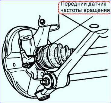
In figure 4, the front speed sensor
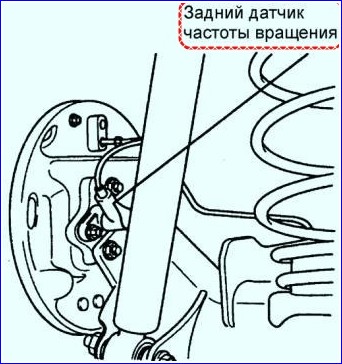
In figure 5, the rear speed sensor
The speed sensor detects the rotation of the wheel and consists of a permanent magnet and a coil.
The front wheel sensors receive information from the gear rotors, located on the drive shafts.
When the teeth of the rotor pass near the sensor, the magnetic field of the sensor changes, as a result of which a voltage pulse is generated.
This voltage is proportional to wheel speed and can be measured.
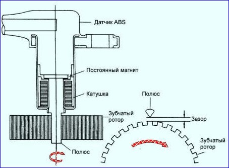
Figure 6 shows the operation of speed sensors
The ABS and EBD warning lamps are located in the instrument cluster
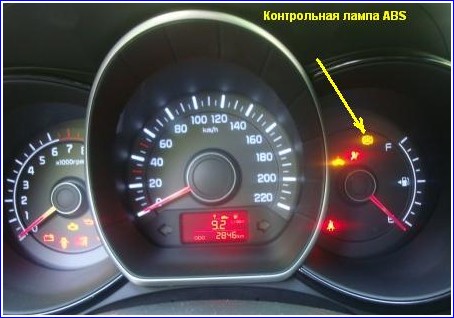
ABS warning light:
- - Lights up for 3 seconds after the ignition is turned on and then goes out.
- - Goes out when the engine starts.
- - If the lamp is constantly on, then there are violations in the ABS.
- - The lamp is on during self-test.
- - If the control lamp lights up intermittently, then there are violations in the ABS and the car's systems work as if the car does not have ABS and TCS systems.
- - The lamp lights up when the electrical connector is disconnected from the ECU control unit.
EBD warning light (electronic brake force distribution):
- - Lights up after the ignition is turned on.
- - Goes out when the engine starts.
- - Lights up when the parking brake lever is applied.
- - Lights up when the brake fluid level is low.
Illuminates when the electronic brake force distribution EBD is not working:
- – in case of a malfunction in the solenoid valve;
- – in case of malfunction in more than one sensor;
- – in case of malfunction of the ECU control unit;
- – when the voltage is exceeded.
Hydraulic Control Unit (HCU)
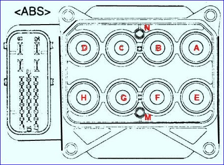
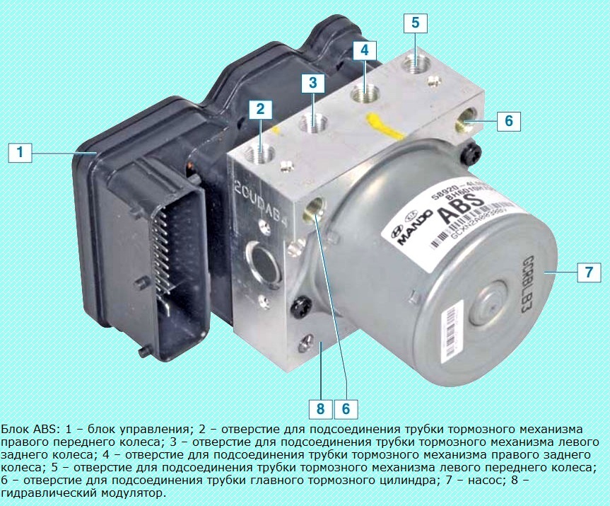
The hydraulic control unit (HCU) consists of a pump with an electric motor and a valve block in order to control the ABS pressure.
The sensor is located in the pump motor and sends an output signal to the ABS unit, which determines the health of the pump.
Front brake fluid pipe port diameter: 4.8mm
Rear brake fluid pipe port diameter: 4.8mm
A dual-circuit pump provides the required pressure, while a valve block distributes the pressure transmitted to the wheel brakes.
- A - front right inlet valve;
- B - rear left inlet valve;
- С - rear right inlet valve;
- D - front left inlet valve;
- E - front right exhaust valve;
- F - rear left exhaust valve;
- G - rear right exhaust valve;
- H - front left exhaust valve;
- M - + engine;
- N - motor (GND).
ABS self-diagnosis
The ABS control unit starts self-diagnostic functions after the ignition is switched on.
The ABS control unit detects a fault for each circuit and component by comparing the system state with a limited set of conditions in the ABS control unit.
The ABS control unit stores the fault code and then outputs it to the diagnostic tool in the form of codes indicated by four digits.
Checking self-diagnosis codes
- 1. Turn the key in the ignition switch to the OFF position and connect the diagnostic tool to the diagnostic socket located near the vacuum booster in the engine compartment.
- 2. Turn the ignition key to the ON position and set the vehicle model and diagnostic tool model on the tool.
- 3. Select the parameter to test after block initialization.
- 4. Press check codes #1 and see if the fault is logged.
The fault code is a four-digit number that appears continuously until the fault code is cleared by the diagnostic tool.
- 5. Based on the list of fault codes, identify the faulty element and restore its functionality.
- 6. After erasing the fault codes from the memory of the ABS control unit, select inspection point №4


