The subframe is the power unit of the front suspension, to which the lower arms of the front suspension, the steering gear, the lower support of the power unit are attached
The subframe consists of two parts, front and back
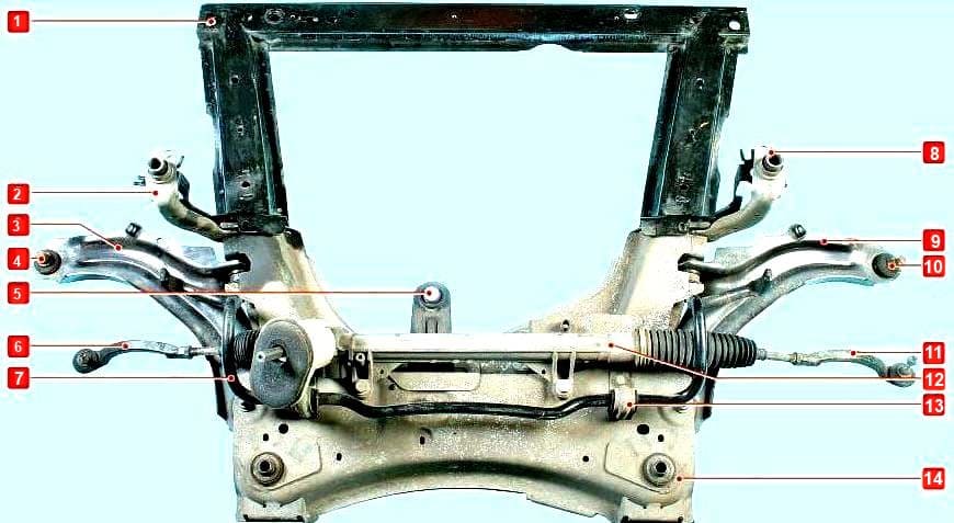
Location of parts of the front suspension subframe: 1 — the front of the subframe; 2.8 — subframe mounting brackets; 3.9 — front suspension arms; 4.10 - ball bearings; 5 - lower support of the power unit; 6.11 — tie rod ends; 7 - bar stabilizer bar; 12 — steering mechanism; 13 - bracket for attaching the stabilizer bar; 14 — rear part of the subframe
The location of the subframe elements is shown in Figure 1.
To remove the subframe, you will need tools: wrenches for 10, 16, 18, tool heads for 16, 18, a flat screwdriver.
Removing the front part of the subframe
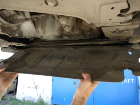
Remove the crankcase protection and engine mudguard.
Remove the front wheel arch liners
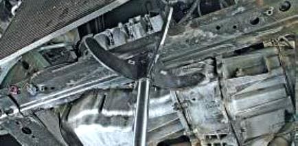
We substitute a support under the front of the subframe
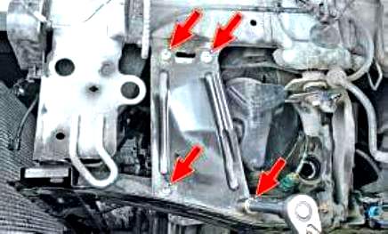
We unscrew the four bolts securing the bracket of the front of the subframe to the body
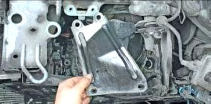
Remove the bracket
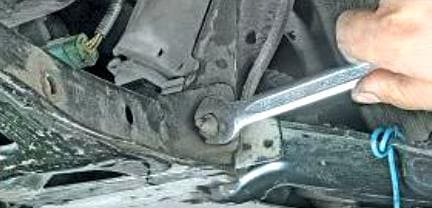
Unscrew the nut securing the front of the subframe to the rear of the subframe.
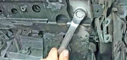
Unscrew the bolt securing the front of the subframe to the body. We also perform all operations on the other side.
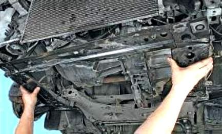
Remove the front part of the subframe.
Removing the rear part of the subframe
Disconnect the negative battery terminal
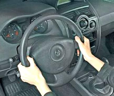
Set the steering wheel to the straight position.
We brake the car with a parking brake and install the rear wheel chocks.
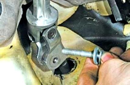
We unscrew the coupling bolt of the terminal connection of the cardan joint of the intermediate shaft to the steering gear shaft.
Loosen the front wheel bolts.
We raise the front of the car and set it on reliable stops.
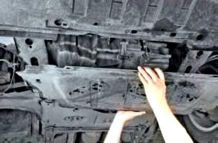
Remove the crankcase protection
Remove the front wheel arch liners
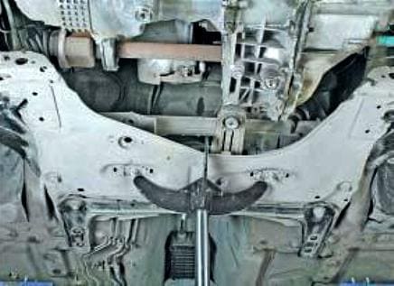
Place the support under the back of the stretcher
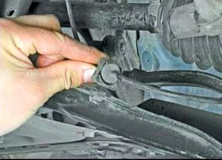
Remove the wheel speed sensor harness holder from the front suspension arm
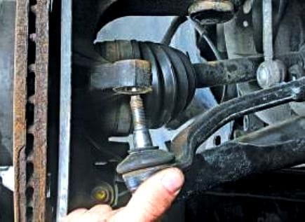
We press the tie rod end pivot pin out of the steering knuckle hole (article - How to replace Renault Megan 2 tie rod ends)
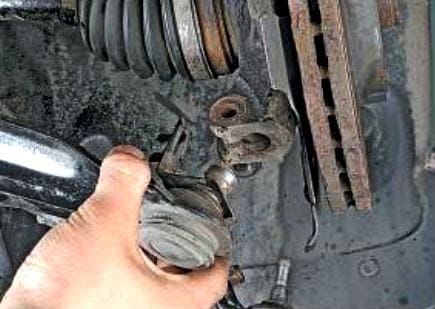
We press the pin of the ball joint of the front suspension arm from the hole of the steering knuckle
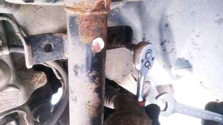
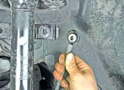
Remove the upper anti-roll bar mount hinge from the shock strut bracket
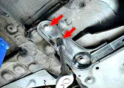
We unscrew the two bolts of the rear subframe bracket
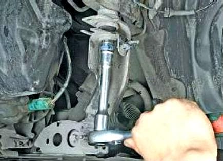
We unscrew the bolt securing the left bracket of the rear of the subframe to the body.
We also do these operations on the other side.
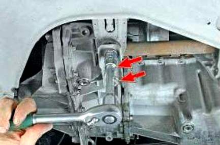
We unscrew the two bolts of the power unit support bracket
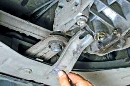
Remove the bracket
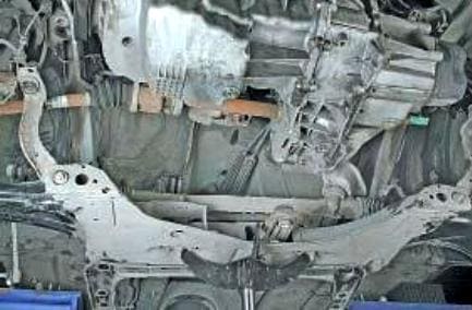
Remove the rear part of the subframe by lowering it on the racks.
Install the parts of the subframe and all the parts in reverse order.
Tightening torques
Nut for fastening the tie rod end to the steering knuckle - 37 Nm
Gimbal clamp clamp bolt - 21 Nm
Ball pin nut - 62 Nm
Subframe mounting bolts - 105 Nm
Subframe mounting nuts - 21 Nm
Nut securing the stabilizer bar to the suspension arm - 14 Nm
Wheel bolts - 105 Nm
For other threaded connections, the tightening torques are as follows:
- M6 - Nm;
- M8 - 25Nm;
- M10 - 50Nm;
- M12 - 105 Nm;
- M14 - 180 Nm;
- M16 - 280 Nm;
- M18 - 400 Nm.
After installation, we check the wheel alignment.


