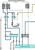
A non-contact ignition system of the DLI type is installed on cars, which provides an increase in the range of setting the ignition timing and voltage of the ignition distributor while reducing electrical interference.
The system includes:
- - ignition coil;
- - camshaft position sensor;
- – ECU ignition control unit;
- - high voltage wires and spark plugs.
In a non-contact ignition system, the camshaft position sensor and the crankshaft angle sensor transmit information to the engine control unit which cylinder needs to be energized.
The engine control unit sends a signal to the appropriate ignition coil, which generates a high voltage current and transmits this current to the spark plug.

In a contactless ignition system, the ignition pulse is applied to two spark plugs at once, one on the compression stroke, one on the exhaust stroke - the ignition spark on the exhaust stroke has no effect on engine operation and is therefore wasted.
Cylinders are grouped according to the firing order of the cylinders. For example, the firing order of the cylinders is 1–3–4–2.
Each ignition coil actually consists of 2 separate high voltage windings that supply a spark to two cylinders each (one to cylinders #1 and 4 and the other to cylinders #2 and 3).
If an inductive tachometer is connected to the spark plug high voltage wire with this ignition system, it will show an engine speed of twice the actual engine speed (i.e. 1600 min–1, instead of the actual 800 min–1).
Electronic ignition timing
The ignition timing is determined and set by the engine control unit based on signals from various sensors and switches.
The engine control unit changes the ignition timing according to engine speed, air intake, coolant temperature and other conditions.
Ignition timing at idle: 8±5° BTDC (6°± 5° for Europe).
The ignition timing is not adjustable.
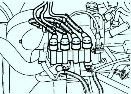
Ignition system components
The ignition system uses two ignition coils located on the engine above the spark plugs for cylinders 2 and 4.
The coil resistance is identical for the two ignition coils.
Ignition coils are maintenance-free and, if defective, must be replaced.
High voltage wires connect the ignition coils to the spark plugs.
They perform basically the same functions as on a conventional ignition system. Due to their shorter length, the energy transferred to the spark plugs increases.
The spark plug is used to transfer the high voltage current generated in the ignition coil to the electrodes in the combustion chamber, where this current produces a spark discharge to ignite the air-fuel mixture.
Ignition timing
Changing the ignition timing setting can be caused by two reasons: a problem with the sensor, which will be detected by the engine control unit or incorrect installation of the camshaft in relation to the crankshaft.
The last problem is related to improper installation of the timing belt.
No adjustment is required after replacing the ignition coil.
Check:
- 1. Start the engine and warm it up to operating temperature.
- 2. Turn off all consumers of electrical energy.
- 3. Connect a tachometer to the engine and a strobe sensor to the high voltage wire of the first cylinder.
- 4. By aligning the marks on the crankshaft pulley with the pointer, check the ignition timing.
Ignition timing: 8±5° BTDC (6°± 5° for Europe) (at idle speed)
The ignition timing is not adjustable.
Ignition coil
Withdrawal:
- 1. Disconnect the cable from the negative battery terminal.
- 2. Disconnect the high voltage wires.
- 3. Disconnect the connectors from the ignition coil.
- 4. Remove the four ignition coil mounting bolts.
- 5. Remove the ignition coils.
Voltage test:
- 1. Disconnect the wire from the negative battery terminal battery.
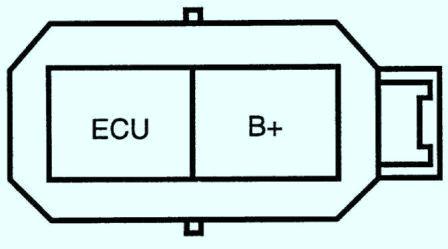
- 2. Disconnect the connector from the ignition coil.
- 3. Turn the ignition key to the "ON" position.
- 4. Measure the voltage between the ECU and B+ terminals at the ignition coil connector. Voltage: 12V
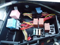
- 5. If there is no voltage, check the fuse, ignition switch and wiring harness.
Resistance test:
- 1. Using an ohmmeter, check the resistance of the primary winding of the ignition coil.
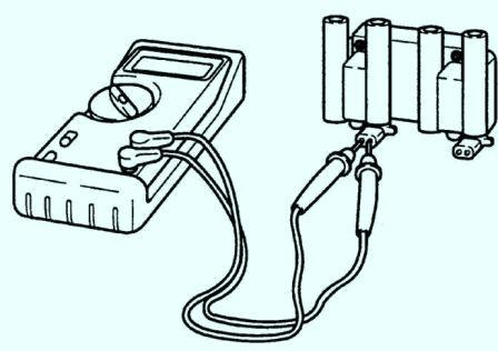
Connect one ohmmeter lead to the positive (+) terminal and the other lead to each negative (–) terminal. If the resistance is not as specified, replace the ignition coil.
Remember that the block contains two coils whose resistance needs to be checked.
Primary resistance: 0.6-0.8 ohm at 20°C
2. Using an ohmmeter, check the resistance of the secondary winding of the ignition coil. If the resistance is not as specified, replace the ignition coil.
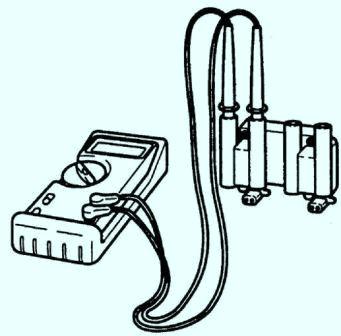
Secondary resistance: 10-15 ohms at 20°C
Installation:
- 1. Install two ignition coils above the spark plugs of cylinders 2 and 4 and press them together.
- 2. Screw four bolts of fastening of the coil of ignition. Tightening torque: 15.6 - 22.6 Nm
- 3. Connect the connectors to the ignition coil.
- 4. Connect high voltage wires
- 5. Connect the wire to the negative battery terminal.
Spark plugs
Withdrawal:
Do not service spark plugs when the engine is hot.
- 1. Disconnect the cable from the negative battery terminal.
- 2. Disconnect the high voltage wires.
- 3. Use compressed air to clean the spark plugs, which will prevent dirt from entering the engine cylinders after unscrewing the spark plugs.
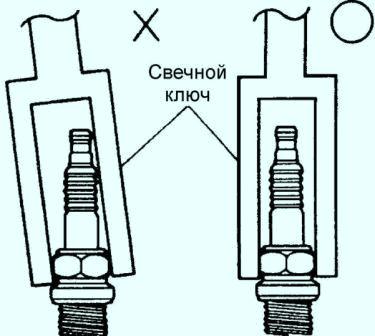
- 4. Unscrew the spark plug using a spark plug wrench. To prevent damage to the candle, install the candle wrench strictly along the axis of the candle.
Check:
- 1. Connect the wire to the negative battery terminal.
- 2. Connect the spark plug to the high voltage wire.
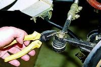
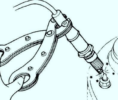
- 3. Holding the spark plug with special pliers with insulated handles, bring the spark plug at a distance of 5–10 mm from the car body.
Do not touch the car body during the following steps.
- 4. The assistant should crank the engine crankshaft with a starter, while a steady strong spark should be observed between the spark plug and the car body.
- 5. If there is no ignition spark or the ignition spark is weak, check the condition and correct the following defects:
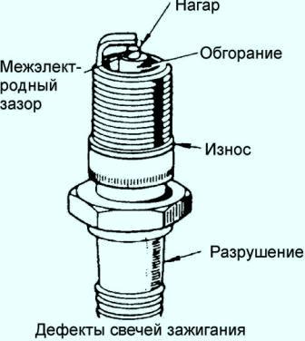
- - if there is carbon deposits, clean or replace the spark plug;
- - clean or replace the spark plug if contaminated with oil;
- - if the electrodes are worn or burnt out, replace the spark plug;
- - if the ceramic insulator is destroyed, replace the spark plug;
- – if the spark plug ring is damaged, replace the spark plug;
- - in case of violation of the interelectrode gap in the spark plug, adjust the gap. The gap is adjusted by bending the side electrode.
The central electrode should never be bent, as this can lead to breakage of the insulator and failure of the candle. To bend the side electrode of the candle, you must use a special tool.
Spark plug gap:
- A3E: 0.8-0.9 mm
- A5D: 0.7-0.8mm
Installation:
- 1. Screw the spark plug into the cylinder head. Tightening torque: 25–30 Nm
- 2. Connect the high voltage wire to the spark plug.
- 3. Connect the wire to the negative battery terminal.
High voltage wires
Check:
- 1. Disconnect the high voltage wires from the spark plugs and ignition coils.
- 2. Clean and check the integrity of the insulation of high voltage wires.
- 3. Check the inner surfaces of the contacts of high-voltage wires for corrosion or deposits.
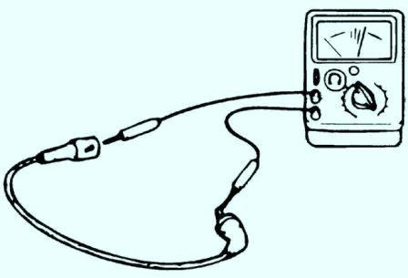
- 4. Measure the resistance of the high voltage wires with an ohmmeter. Resistance: 4.48-6.72 kΩ/m
- 5. If there is any defect, replace the high voltage wire.
")
")
")
")
")
")