")
")
")
")
")
")
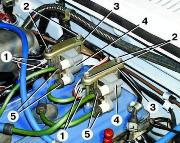
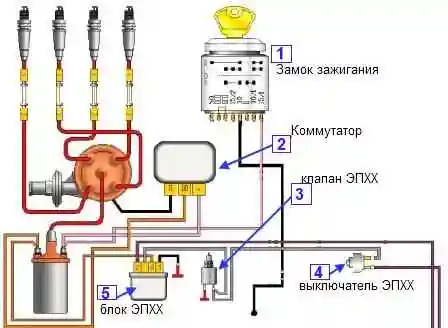
The ZMZ-402 and ZMZ-4021 engines are equipped with a non-contact ignition system, consisting of a transistor switch, ignition distributor type 19.3706, ignition coil type B116 or B116-01, spark plugs and high-voltage and low-voltage wires
Ignition distributor (1908.3706) - non-contact, with a sensor (generator) of control pulses and built-in vacuum and centrifugal ignition timing controllers.
The distributor sensor performs two functions: it sets the moment of sparking and distributes high voltage pulses to the cylinders in accordance with the order of their operation.
For this purpose, a slider is used, put on the shaft of the distribution sensor.
An interference suppression resistor* is installed in the slider.
On part of the sensors, instead of a resistor, a cover with a central carbon contact is installed.
The switch (1313734) opens the power circuit of the primary winding of the ignition coil, converting the control pulses of the sensor into current pulses in the ignition coil.
Ignition coil
Withdrawal
Unscrew the nuts 1 and disconnect the low-voltage wires from the coil terminals 3.
Disconnect high voltage wire 4 from the ignition coil.
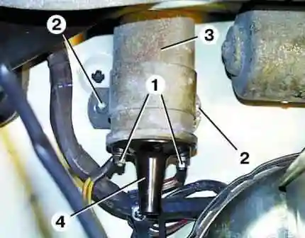
Unscrew nuts 2 and remove coil 3 (fig. 2).
Check
Ignition coils B116 and B116-01 are checked at the stand mod. K–295.
The coil must ensure uninterrupted sparking on a spark gap with a gap of 7 mm at a speed of rotation of the ignition distributor shaft of at least 2500 min –1.
Inspect the coil. If there are chips, cracks, signs of heating or oil leakage on the plastic cover, replace the coils.
Check the primary resistance of the ignition coil by connecting an ohmmeter between the low voltage terminals.
The ohmmeter should show a resistance of 0.48-0.72 ohms.
Then check the resistance of the secondary winding by connecting an ohmmeter between the high voltage terminal and the "K" terminal of the coil.
The ohmmeter should read between 13,200 and 19,800 ohms. If the measured parameters differ, the coil must be replaced.
Ignition switch
The transistor switch type 131.3734 or 90.3734 is mounted on the left mudguard behind the battery.
It converts the control pulses of the Hall sensor in the ignition distributor into current pulses in the primary winding of the ignition coil.
Since the switch generates a large amount of heat during operation, it is necessary to periodically clean the switch case from dirt and dust and do not cover it with foreign objects.
Check
Remove the switch from the car by unscrewing the two mounting nuts and disconnecting the wires.
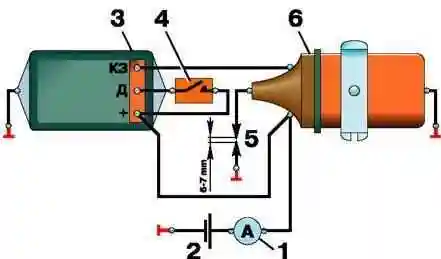
Assemble the circuit shown in Figure 3 on a suitable metal plate.
Fix the tip of high voltage wire 5 at a distance of 6–7 mm from the plate.
When switch 4 is turned on, ammeter 1 should show a current within 6-7 A, and after 1-3 seconds, the current should drop to 0.
At the moment the switch 4 is turned off, a spark should jump between the tip of the high voltage wire 5 and the plate (permanent sparking is possible).
Otherwise switch 3 is defective and must be replaced.