We examined the disassembly of the gearbox in the article: - “Disassembly of the gearbox”
After we have washed and debugged the parts of the gearbox, we proceed to the assembly
Conventionally, we have already installed the bearings and the differential.
We install at the same time the secondary shaft assembly, the first and second gear fork and the input shaft (Fig. 1)
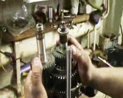
We install clamps (bosses) in the sockets (Fig. 2)
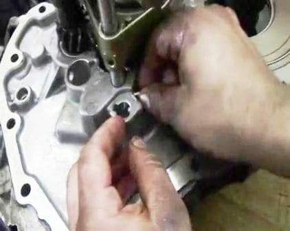
Install the fork of the third and fourth gear (Fig. 3)
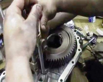
We hammer the pin of the fork of the third and fourth gears with a hammer (Fig. 4)
All forks must be in neutral, father-in-law is not in any gear.
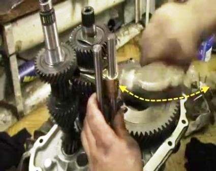
Installing the reverse speed clutch (Fig. 5)
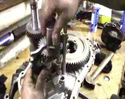
Insert the fifth gear fork guide (Fig. 6)
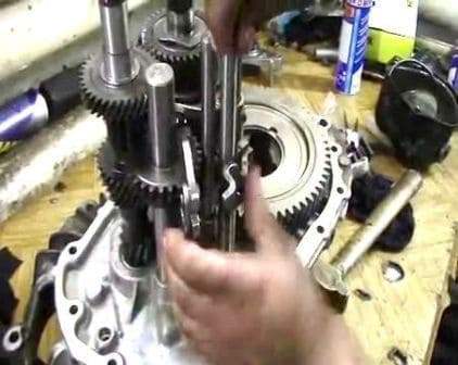
We hammer in the locking pin of the reverse gear clutch (Fig. 7)
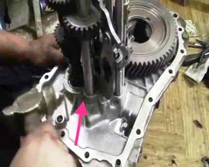
Before installing the gearbox housing, you need to turn on the third gear (Fig. 8)
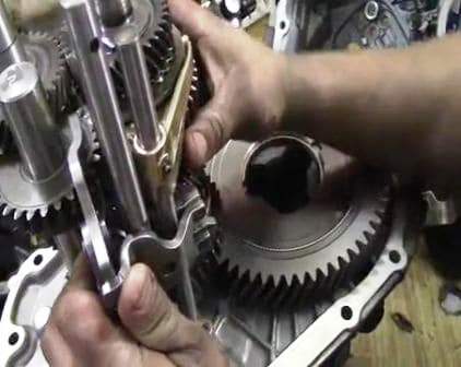
This is necessary so that the leash that is in the crankcase (Fig. 9) is installed in the third gear fork (Fig. 10)
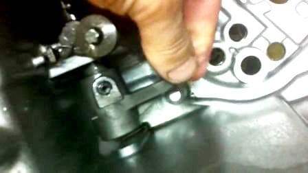
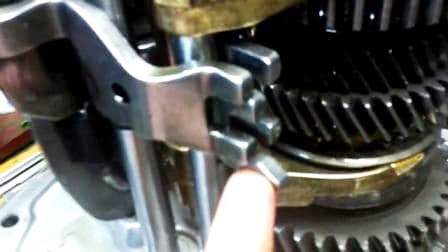
Lubricate the junction of the crankcase with sealant (Fig. 11)
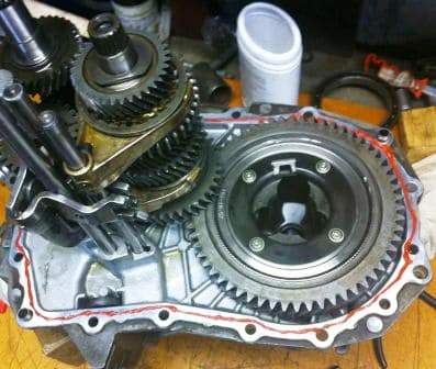
We put the magnet in a special pocket in the gearbox housing (Fig. 12)
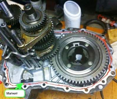
Insert the oil chute into the crankcase (Fig. 13)
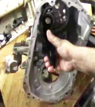
We move the lever to the third gear position and start installing the gearbox housing (Fig. 14)
(We perform this operation together) At the beginning of the installation of the gearbox housing, the fifth gear stem comes out first.
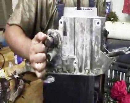
Before it exits, we insert the spring and the retainer ball and hold it (Fig. 15).
The assistant lowers the gearbox housing at this time. The rod comes out of the crankcase hole and the retainer remains in place.
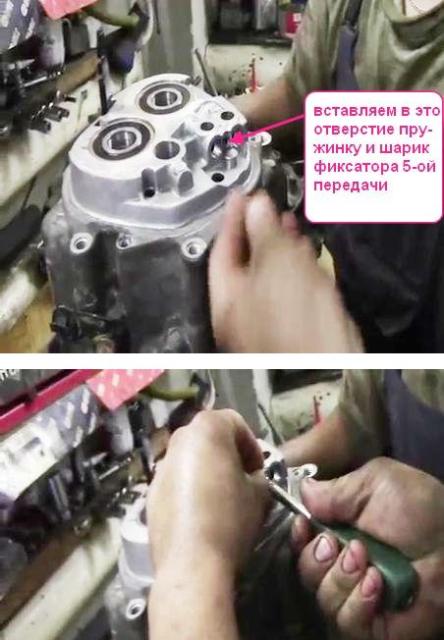
In the same way, we insert the latches and the stem of the first and second speed swarm (Fig. 16)
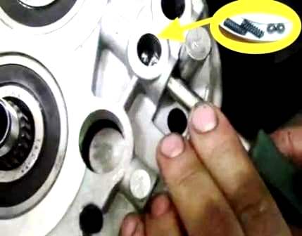
Next, insert the latch and the stem of III and IV gears (Fig. 17)
After the crankcase is connected, you need to check how the gears are engaged.
If all gears turn on, then the assembly was correct.
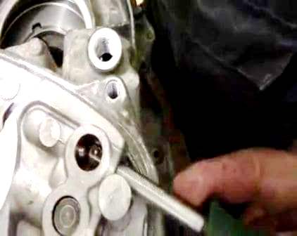
We bait and tighten 16 bolts for fastening the gearbox housings (Fig. 18).
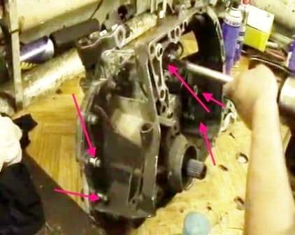
Before fully tightening the bolts, you must first rotate the input shaft to self-align the bearings.
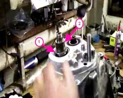
We install a thrust washer on the input shaft (the correct position of the bushing is in Figure 8 of the article on disassembling the gearbox) and the gear bushing (Fig. 19)
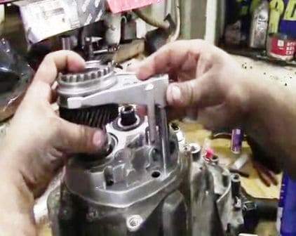
Install the fifth gear together with the synchronizer and fork (Fig. 20)
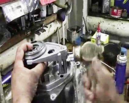
We hammer the pin into the fifth gear fork (Fig. 21)
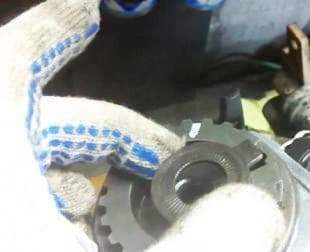
Install the lock washer (Fig. 22)
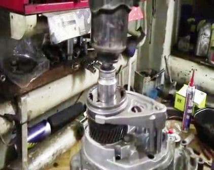
We bait and tighten the nut of the rear end of the input shaft (Fig. 23) (we tighten it with a torque of 190 Nm)
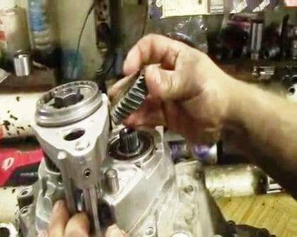
Install the driven gear of the fifth gear on the secondary shaft (Fig. 24)
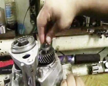
We bait and tighten the bolt of the rear end of the secondary shaft (Fig. 25) (tightening torque 70 Nm)
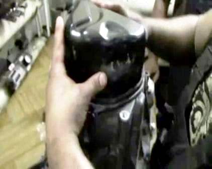
We install a new sealing ring and install the rear cover of the gearbox housing (Fig. 26)
Tighten the three bolts of the rear cover.
Tightening torques for gearbox components:
Knot - Tightening torque Nm
- Gearbox 3 fill plug
- Bolts securing gearbox housing to clutch housing 25
- After shaft rear end bolt 70
- Nut, input shaft rear end 190
- Rear cover bolts 25
- Reversing light switch 25
- Clutch slave cylinder bolt 21
- Shift shaft bolt 20
- Leash bolt 10
- Reverse fork stem bracket bolt 25
- Drain plug 25
- Shift shaft retainer 21-23
- Gearbox housing to clutch housing bolts with Loctite 63
- Remaining bolts securing the gearbox housing to the clutch housing 52
- 120 final drive gear bolts
- Reverse fork bracket mounting bolts 15


