In a fuel supply system without a fuel return line to the tank, the fuel supply pressure does not depend on engine load

The power supply system includes elements of the following subsystems:
- - fuel supply, including a fuel tank, an electric fuel pump with a filter, a fuel pressure regulator, pipelines and a fuel rail with injectors;
- - air supply system, consisting of an air supply hose, an air filter, a throttle assembly, an idle speed controller;
- - fuel vapor recovery, which includes an adsorber, a control valve and connecting pipelines.
The functional purpose of the supply subsystem is to ensure the supply of the required amount of fuel to the engine in all operating modes.
The engines are equipped with an electronic engine management system with multiport fuel injection.
In the multiport injection system, the functions of mixture formation and dosing of the air-fuel mixture supply to the engine cylinders are separated.
Air is supplied by an air supply subsystem consisting of a throttle assembly, and the amount of fuel required at each moment of engine operation is injected into the intake pipe by nozzles.
This control method makes it possible to ensure the optimal composition of the combustible mixture at each particular moment of engine operation, which allows you to get maximum power with the lowest possible fuel consumption and low exhaust gas toxicity.
The fuel injection system (as well as the ignition system) is controlled by an electronic unit that continuously monitors the engine load, the vehicle speed, the thermal state of the engine, and the optimal combustion process in the engine cylinders using appropriate sensors.
The fuel vapor recovery system prevents fuel vapors from escaping into the atmosphere, which adversely affect the environment.
The system uses the method of vapor absorption by a carbon adsorber.
Fuel vapors from the fuel tank are constantly discharged through the pipeline and accumulate in the adsorber filled with activated carbon (adsorbent).
When the engine is running, the adsorbent is regenerated (recovered) by blowing the adsorber with fresh air entering the system under the action of vacuum transmitted through the pipeline from the receiver to the adsorber cavity when the valve is opened.
The value of the valve opening, and, consequently, the intensity of the canister purge depends on the throttle valve opening angle and is determined by the vacuum that occurs in the receiver cavity of a running engine.
Fuel vapors from the adsorber through the pipeline enter the engine receiver and burn in the cylinders.
Failures in the evaporative emission system can lead to unstable idling, engine shutdown, increased toxicity of exhaust gases and poor driving performance.

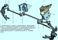
The main sensor for ensuring an optimal combustion process is the oxygen concentration sensor in the exhaust gases (lambda probe).
It is installed on the engine exhaust manifold and, together with the electronic unit and injectors, forms a circuit for adjusting the composition of the air-fuel mixture supplied to the engine

Scheme of the air-fuel ratio control loop: 1 - injector; 2 - exhaust manifold; 3 - oxygen concentration sensor in exhaust gases (lambda probe); 4 - engine; 5 - electronic engine control unit; 6 - catalytic converter of exhaust gases; 7 - diagnostic oxygen concentration sensor
Based on the sensor signals, the engine control unit determines the amount of unburned oxygen in the exhaust gases and, accordingly, evaluates the optimal composition of the air-fuel mixture entering the engine cylinders at any given time.
Having fixed the deviation of the composition from the optimal 1:14 (respectively, fuel and air), which provides the most efficient operation of the exhaust gas catalytic converter, the control unit changes the composition of the mixture using injectors.
As a result, the air-fuel ratio control loop is closed.
There are two oxygen concentration sensors installed on the car: the first is on the exhaust manifold, the second is after the catalytic converter.
The first sensor is control (based on its signal, the ECU corrects the fuel supply), and the second is diagnostic (based on its signal, the ECU evaluates the efficiency of the catalytic converter)

The fuel tank, molded from petrol-resistant plastic, is installed under the floor of the body at the rear. so that fuel vapors do not enter the atmosphere, the tank is connected by a pipeline to the adsorber.
An electric fuel pump is installed in the flanged hole in the upper part of the tank.
From the pump, fuel is supplied through the pressure regulator to the fuel filter installed at the end of the fuel tank, and from there it enters the engine fuel rail mounted on the intake pipe.
From the fuel rail, fuel is injected by injectors into the intake pipe.
The fuel lines of the power supply system are tubes connecting various elements of the system.
The hoses of the power system are made using a special technology from oil and petrol resistant materials.
The use of hoses that differ in design may lead to a failure of the power system, and in some cases, to a fire.
Round sealing rings are used in the connections of pipelines with elements of the power system.
The use of seals of a different design is prohibited.

The fuel pump module includes an electric pump, a fuel fine filter, a fuel pressure regulator and a fuel gauge sensor.

The fuel pump module delivers fuel and is installed in the fuel tank, which reduces the possibility of vapor lock because the fuel is supplied under pressure, not under vacuum.
Submersible fuel pump, electrically driven, rotary type.
The pump of a non-separable design cannot be repaired; if it fails, it must be replaced.

Fuel rail: 1,3,4 - fuel injector harness holders; 2.5 - fuel rail mounting brackets; 6 - fitting of the fuel supply hose; 7,8,10,11 - fuel injector fittings; 9 - ramp
Ramp 9 (Fig. 6) of the injectors is a cast hollow part with fittings for installing injectors and with fitting 6 for connecting the high pressure fuel line.
The nozzles are sealed in their sockets with rubber rings and secured with spring clips.
The injector rail assembly is inserted with injector shank into the intake pipe holes and secured with two bolts.

Nozzle: 1.3 - O-rings; 2 - plug terminals of the electromagnet winding
The injectors are attached to the rail from which fuel is supplied to them, and with their nozzles they enter the intake pipe openings.
In the openings of the ramp and the inlet pipe, the nozzles are sealed with rubber sealing rings 1 and 3 (Fig. 7).
The injector is designed for metered injection of fuel into the engine cylinder and is a high-precision electromechanical valve.
Fuel under pressure comes from the rail through the channels inside to nozzle body to the shut-off valve.
A spring compresses the check valve needle against the taper hole in the atomizer plate, keeping the valve in the closed position.
The voltage supplied from the engine control unit through plug-in terminals 2 to the injector solenoid winding creates a magnetic field in it, which draws the core together with the shut-off valve needle into the solenoid.
A conical annular hole in the atomizer plate opens and fuel is injected through the diffuser of the atomizer body into the inlet port of the cylinder head and further into the engine cylinder.
After the electrical impulse stops, the spring returns the core and needle of the shut-off valve to its original state - the valve closes. The amount of fuel injected by the injector depends on the duration of the electrical impulse.

The fuel pressure regulator is installed on the fuel rail (can be installed in the fuel module) and is designed to regulate the fuel pressure in the fuel rail depending on the air pressure in the intake manifold.
Excess fuel from the fuel rail is returned to the fuel tank through the fuel pressure regulator valve through the return line.

The air filter is installed in the left side of the engine compartment.

The filter element of the air filter is paper, flat, with a large area of the filtering surface.

Throttle assembly: 1 - throttle control motor cover; 2 - fitting of the adsorber purge valve hose; 3 - throttle valve; 4 - electrical connector; 5 - inlet pipe
The throttle assembly (Fig. 11) is the simplest control device and serves to change the amount of main air supplied to the engine intake system.
It is mounted on the inlet flange of the intake manifold. The inlet pipe of the air intake chamber is put on the inlet pipe of the throttle assembly.
The throttle assembly includes a throttle control stepper motor.
There is no mechanical connection between the throttle assembly and the throttle control pedal.
The so-called "electronic throttle pedal" transmits information about the degree of depression on the pedal to the electronic engine control unit, which, in turn, taking into account the vehicle speed, gear engaged, engine load and engine speed, opens the throttle valve to the required angle .
Faults related to the fuel injection system
Cars use a multiport fuel injection system.
Spread injection is called because fuel is injected into each cylinder by a separate injector.
The fuel injection system reduces the toxicity of exhaust gases while improving driving performance and fuel efficiency of the car.
In the fuel injection system of an engine with feedback, an exhaust gas catalytic converter and two oxygen concentration sensors are installed in the exhaust system, which provide feedback.
Sensors monitor the oxygen content in the exhaust gases, and the electronic control unit, using their signals, maintains such an air-to-fuel ratio at which the converter works most efficiently.
Before removing any components of the injection control system, disconnect the wire from the negative terminal of the battery.
Disconnect the battery only when the ignition is off.
Do not start the engine if the cable lugs on the battery are loose.
Never disconnect the battery from the vehicle's electrical system while the engine is running.
When charging, disconnect the battery from the car's on-board network.
Do not allow the electronic control unit (ECU) to heat up above 65°C in working condition and above 80°C in non-working condition (for example, in a drying chamber after races).
If this temperature is exceeded, the computer must be removed from the vehicle.
Do not disconnect or connect the wiring harness connectors to the ECU while the ignition is on.
Before performing arc welding on a vehicle, disconnect the wires from the battery and the wire connectors from the ECU.
Perform all voltage measurements with a digital voltmeter, the internal resistance of which is at least 10 MΩ
Electronic components used in the injection system are designed for very low voltage, so they can easily be damaged by electrostatic discharge.
To prevent ESD damage to the ECU:
- - do not touch the computer plugs or electronic components on its boards with your hands;
- - when working with a programmable read-only memory (PROM) of the control unit, do not touch the pins of the microcircuit.
When working in rainy weather, do not allow water to get on the electronic components of the fuel injection system.
Check the injection system in the following order
Check the ground connection of the engine and battery.
Check pressure regulator, fuel filter and fuel pump.
Check the fuses and relays for switching on the injection system elements.
Check the reliability of the contacts of the pads with the wires of the injection system elements.
Check the sensors of the injection system.
")
")
")
")
")
")