")
")
")
")
")
")
Checking the electrical circuit
The electrical circuit consists of switches, relays, electric motors, fuses, circuit breakers, wires and connectors that connect the current consumer to the battery and body.
For help in finding sources of malfunction of the electrical system, the article provides diagrams of the electrical equipment of the car.
Before attempting to determine the source of a malfunction, study the appropriate electrical circuit diagram to get an idea of the elements of this circuit.
The number of possible sources of malfunction can be reduced by checking the operation of other elements included in this circuit.
If several elements or circuits fail at the same time, the fuse common to these circuits or elements may be defective, or the connection to the body - “ground” is broken.
The causes of the malfunction are loose or oxidized connectors, poor contact with the body, blown fuses or faulty relays.
Visually check the condition of all fuses, wires and connectors in the failed circuit before proceeding to check the rest of the elements.
Use the wiring diagrams to determine the end clamps that need to be checked to determine the source of the problem.
The main instruments needed to locate the source of a malfunction are a tester or voltmeter, a 12 V test lamp, an ohmmeter, a battery, and a set of wires with probes, preferably with a circuit breaker or fuse that is used to bypass the wires or elements being tested.
In addition to a broken connection of wires in an electrical system, two more main types of malfunctions are possible - disconnection of the circuit or short circuit.
The circuit opens due to an open circuit, as a result, the current is interrupted, causing the electrical equipment to turn off.
To determine the continuity of the circuit, connect a circuit tester or voltmeter: one lead to the negative terminal of the battery or a grounded element, the other to the contact in the circuit under test, preferably closest to the battery or fuse.
The section of the circuit under test must be powered by the battery, unless the battery connector is not conducting current or the fuse is blown (remember that some electrical equipment circuits turn on only when the key is turned in the ignition switch to a certain position).
Turn on the circuit, then connect the tester probe to the connection closest to the circuit breaker on the side of the element being tested.
If there is voltage (as evidenced by the light of the test lamp or the voltmeter reading), then there are no breaks in the section of the circuit between the corresponding connection and the switch.
If a section is found where there is no voltage, then an open circuit occurred between this point and the point of the previous test, where there was voltage.
An open circuit is caused by a damaged or loose connector.
To detect the source of a short circuit, turn off electrical consumers - lamps, electric motors, heating elements, etc.
Remove the appropriate fuse and connect the tester or voltmeter leads to the fuse contacts.
Turn on the power to the circuit; do not forget that some electrical circuits are switched on only when the key in the ignition switch is turned to a certain position.
If there is voltage in the circuit (as indicated by the ignition of the test lamp or the reading of the voltmeter), then there is a short circuit in the circuit.
If there is no voltage during the test, and the fuse still blows when the same load is connected, the load element has failed.
The negative terminal of the battery is connected to the "mass" - the body, engine or gearbox.
Insecure or oxidized fastening may cause the element to fail or malfunction.
Be aware that many vehicles use "mass" wires between certain elements such as the engine/transmission and the body, i.e. in places where there is no direct contact between metal elements due to soft rubber mounts or a layer of paint.
To check the reliability of the cell grounding, disconnect the battery and connect one of the ohmmeter leads to a reliably grounded cell.
Connect the other lead to the wire or body connection to be tested.
The resistance indicated by the ohmmeter must be zero, otherwise check the connection as described below.
If the reliability of contact with the ground is in doubt, disassemble the connection, remove dirt and clean the contacts.
When reassembling, tighten the connector retainer by applying a coat of petroleum jelly or silicone lubricant to seal the connector corrosion prevention.
A continuity test is performed to make sure that a circuit, its section or element conducts current.
Disconnect the wires from the battery terminals and connect a test light probe with its own power source, such as a continuity tester, to one end of the circuit and the other probe to the other end of the circuit.
If the lamp lights up, it means that the circuit is not interrupted and conducts electricity. Switches can be checked in the same way.
Connection diagram of the front wiring harness VAZ-2123
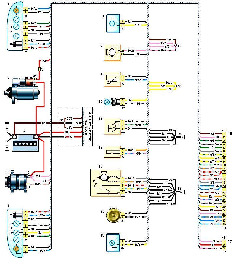
Scheme of connections of the front wiring harness BA3-2123: 1 - block headlight, right; 2 - starter; 3 - pads of the front harness and wires of the starter traction relay; 4 - battery; 5 - generator; 6 - block headlight left; 7 - fog lamp right; 8 - washer motor; 9 - outdoor air temperature sensor; 10 - engine compartment lamp; 11 - engine compartment lamp switch; 12 - brake fluid level sensor; 13 - windshield wiper motor; 14 - sound signal; 15 - fog lamp left; 16, 17 - pads for connecting to the instrument panel wiring harness
VAZ-2123 instrument panel wiring diagram
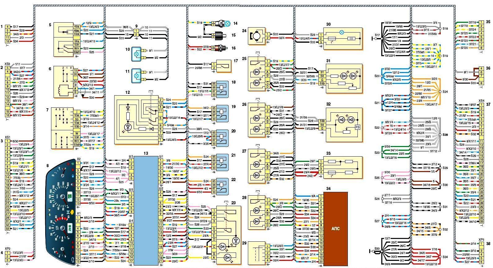
Connection diagram of the wiring harness for the instrument panel BA3-2123: 1 - diagnostic block; 2 - block connection with the wiring harness of the engine control system; 3, 4 - pads for connecting to the front wiring harness; 5 - left steering column switch; 6 - ignition switch; 7 - right steering column switch; 8 - instrument cluster; 9 - connection block with the wiring harness for the illumination of the heating, ventilation and air conditioning control unit; 10.11 - backlight lamps for the heating, ventilation and air conditioning control unit; 12 - alarm switch; 13 - mounting block of fuses and relays; 14 - ceiling light for the glove box; 15 - glove box cover switch; 16 - brake signal switch; 17 - horn switch; 18- fog lamp relay; 19 - power window relay; 20 - horn relay; 21 - seat heating relay; 22 - starter relay; 23 - outdoor lighting switch; 24 - heater fan motor; 25 - switch for heating the glass of the tailgate; 26 - fog lamp switch; 27 - rear fog light switch; 28 - air conditioner switch; 29 - heater motor switch; 30 - cigarette lighter; 31 - headlight beam direction regulator; 32 - brightness control for instrument illumination; 33 - additional heater fan resistor; 34 - control unit of the automobile anti-theft system; 35, 36 - pads for connecting to the head sound reproduction device; 37, 38 - connection pads with rear wiring harness
Connection diagram of the rear wiring harness VAZ-2123
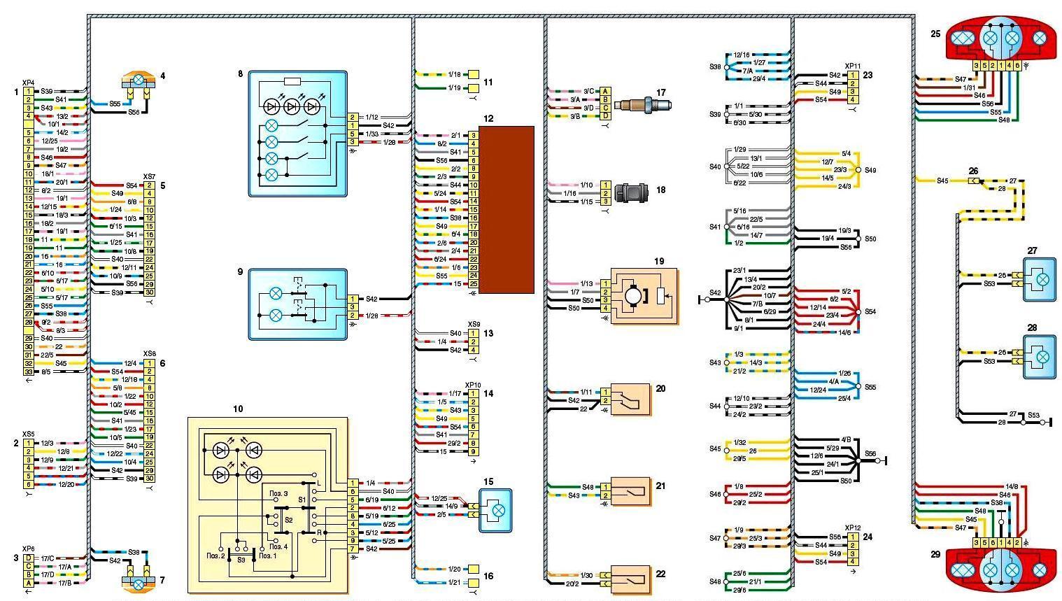
Scheme of connections of the rear wiring harness BA3-2123: 1, 2 - block connection with the wiring harness of the instrument panel; 3 - block connection with the wiring harness of the engine control system; 4 - right side direction indicator; 5 - block connection with the wiring harness of the right front door; 6 - block connection with the wiring harness of the left front door; 7 - left side direction indicator; 8 - ceiling lamp for interior lighting; 9 - plafond of individual lighting; 10 - switch for exterior rear-view mirrors; 11 - block for connecting the right rear speaker; 12 - power pack control unit; 13 - block connection with the wiring harness for heating the front seats; 14 - block connection with the wiring harness of the tailgate; 15 - trunk lighting cover; 16 - block for connecting the left rear speaker; 17 - diagnostic oxygen concentration sensor; 18 - vehicle speed sensor; 19 - fuel pump; 20 - switch of the signaling device for turning on the parking brake; 21 - reverse light switch; 22 - differential lock enable sensor; 23 - connect block niya with a plait of wires of the right back door; 24 - block connection with the wiring harness of the left rear door; 25 - rear right lamp; 26 - connection block with a wiring harness for license plate lights; 27, 28 - license plate lights; 29 - rear left lamp
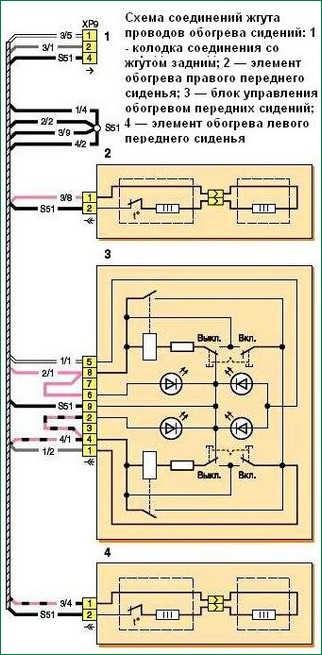
Heated seat wiring harness connection diagram
Auxiliary Wiring Harness Connection Diagram (Tailgate)
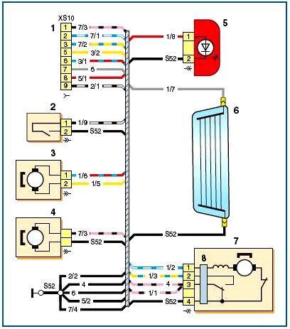
Scheme of connections of the additional wiring harness (tailgate): 1 - block connection with the rear harness; 2 - tailgate limit switch; 3 - motor-reducer for locking the tailgate lock; 4 - the electric motor of the glass washer of the tailgate; 5 - additional braking signal; 6 - element for heating the glass of the tailgate; 7 - tailgate glass cleaner; 8 - tailgate glass cleaner relay
Wiring harness wiring diagram for left and right rear doors

Connection diagram of the wiring harnesses of the left and right rear doors: 1, 2 - connection blocks with the rear harness; 3 - motor-reducer for blocking the lock of the right door; 4 - limit switch of the right door; 5 - limit switch of the left door; 6 - motor-reducer for blocking the lock of the left door
Connection diagram of the wiring harnesses of the left and right front doors of the VAZ-2123
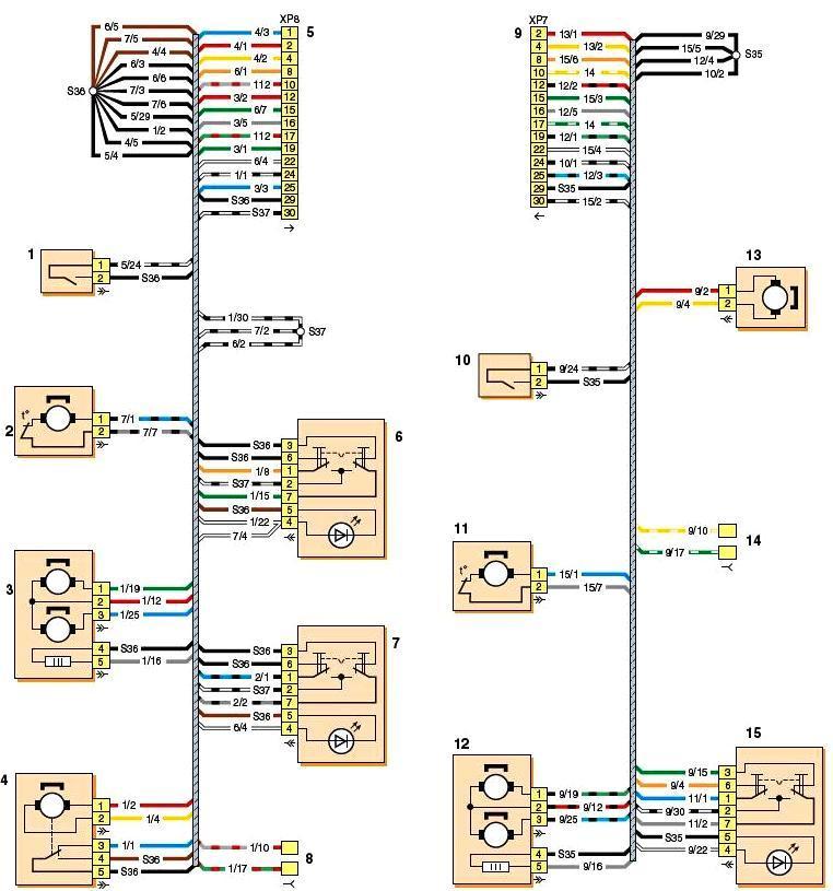
Wiring harness wiring diagram for left and right front doors BA3-2123: 1 - left door limit switch; 2 - motor-reducer of the power window of the left door; 3 - electric drive of the external rear-view mirror; 4 - motor-reducer for blocking the lock of the left door; 5 - block connection with the rear harness; 6 - power window switch of the left door; 7 - power window switch of the right door; 8 - pads for connection with the left loudspeaker; 9 - block connection with the rear harness; 10 - limit switch of the right door; 11 - motor-reducer of the window regulator of the right door; 12 - electric drive of the outside rear-view mirror; 13 - motor-reducer for blocking the lock of the right door; 14 - pads for connection with the right loudspeaker; 15 - power window switch, right door
Connection diagram of the wiring harness of the VAZ-2123 engine control system
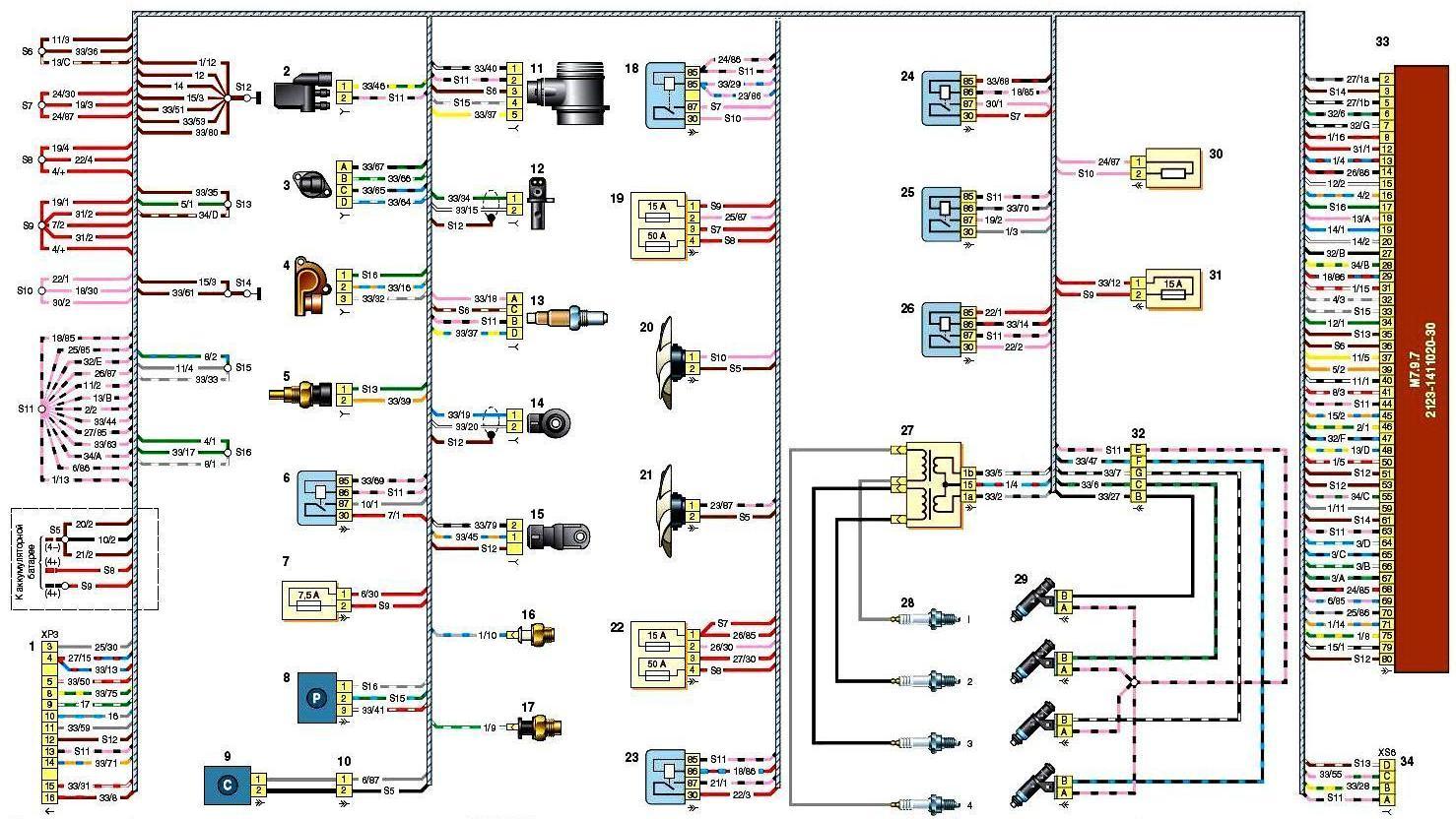
Connection diagram of the wiring harness of the engine management system BA3-2123: 1 - block connection with the wiring harness of the instrument panel; 2 - adsorber purge valve; 3 - idle speed regulator; 4 - throttle position sensor; 5 - coolant temperature sensor; 6 - air conditioner compressor relay; 7 - air conditioner compressor relay fuse; 8 - refrigerant pressure sensor; 9 - air conditioner compressor; 10 - block connection with the wiring harness of the air conditioning compressor; 11 - mass air flow sensor; 12 - crankshaft position sensor; 13 - control oxygen concentration sensor; 14 - knock sensor; 15 - phase sensor; 16 - low oil pressure sensor; 17 - coolant temperature indicator sensor; 18 - relay of the right fan of the cooling system; 19 - fuse block protecting the circuits of the right fan and the fuel pump relay; 20 - the right fan of the system is cooled and I; 21 - left fan of the cooling system; 22 - fuse block protecting the circuits of the left fan and the ignition relay; 23 - relay of the left fan of the cooling system; 24 - additional relay; 25 - fuel pump relay; 26 - ignition relay; 27 - ignition coil; 28 - spark plugs; 29 - nozzles; 30 - additional resistor; 31 - controller power circuit fuse; 32- block connection with the wiring harness of the injectors; 33 - engine control unit (controller); 34 - connection block with rear wiring harness