")
")
")
")
")
")
ECM sensors and controller ME17.9.71 for the EURO-5 toxicity standards of a Chevrolet Niva car
The electronic engine control system (ECM) consists of a controller, sensors for engine and vehicle operation parameters, as well as actuators
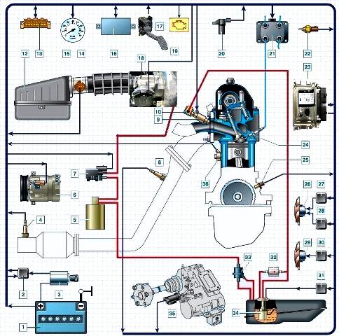
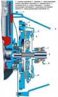
Scheme of the electronic engine control system: 1 - battery; 2 - main relay; 3 - ignition lock; 4 - diagnostic oxygen concentration sensor; 5 - adsorber; 6 - air conditioner compressor; 7 - adsorber purge valve; 8 - control oxygen concentration sensor; 9 - nozzle; 10 - fuel rail; 12 - air filter; 13 - diagnostic connector; 14 - mass air flow sensor; 15 - tachometer; 16 - immobilizer block; 17 - electronic gas pedal; 18 - throttle assembly; 19 - control lamp for a malfunction of the engine management system; 20 - phase sensor; 21 - ignition coil; 22 - coolant temperature sensor; 23 - controller; 24 - spark plug; 25 - crankshaft position sensor; 26 - right fan of the cooling system; 27 - additional relay; 28 - relay of the right fan of the cooling system; 29 - left fan of the cooling system; 30 - relay of the left fan of the cooling system; 31 - fuel pump relay; 32 - fuel filter; 33 - gravity valve; 34 - fuel module; 35 - speed sensor; 36 - knock sensor
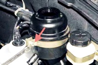
Controller
The controller is a mini-computer for special purposes, it consists of random access memory (RAM), programmable read-only memory (PROM) and electrically reprogrammable memory (EPROM).
RAM is used by the microprocessor to temporarily store current information about the operation of the engine (measured parameters) and calculated data.
Also, fault codes are written to the RAM.
This memory is volatile, i.e. when the power is interrupted (disconnecting the battery or disconnecting the wiring harness block from the controller), its contents are erased.
EPROM stores the engine control program, which contains a sequence of operating commands (algorithms) and calibration data (settings).
PROM determines the most important parameters of engine operation: the nature of the change in torque and power, fuel consumption, ignition timing, composition of exhaust gases, etc. PROM is non-volatile, i.e. the contents of its memory do not change when the power is turned off.
ERPROM stores controller, engine, and vehicle IDs. Records operating parameters, as well as violations of engine and vehicle operation. It is a non-volatile memory.
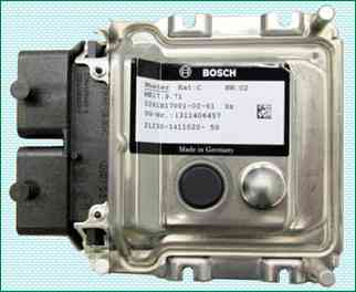
The controller is the central unit of the engine control system.
It receives information from sensors and controls the actuators, ensuring optimal engine operation at a given level of vehicle performance.
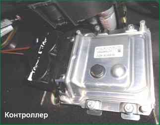
The controller is located in the area of the passenger's feet and is attached to the bulkhead.
The controller controls actuators such as fuel injectors, motorized throttle, ignition coil, oxygen sensor heater, canister purge valve, and various relays.
The controller controls the on and off of the main relay (ignition relay), through which the supply voltage from the battery is supplied to the elements of the system (except for the electric fuel pump, electric fan, control unit and APS status indicator).
The controller turns on the main relay when the ignition is turned on.
When the ignition is turned off, the controller delays turning off the main relay for the time necessary to prepare for the next turn on (completion of calculations, setting the throttle to the position before starting the engine).
When the ignition is turned on, the controller, in addition to performing the functions mentioned above, exchanges information with the APS (if the immobilization function is enabled).
If the exchange determines that access to the vehicle is allowed, then the controller continues to perform engine control functions. Otherwise, the engine will be blocked.
The controller also performs a system diagnostic function.
It defines on The presence of malfunctions of the system elements, turns on the signaling device and stores codes in its memory that indicate the nature of the malfunction and help the mechanic to carry out repairs.
Mass air flow sensor
The engine control system uses a hot-wire type MAF with a frequency response of a digital output signal.
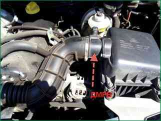
It is located between the air filter and the intake pipe hose.
The MAF signal is a frequency (Hz) signal, the pulse repetition rate of which depends on the amount of air passing through the sensor (increases with increasing air flow).
The scan tool reads the sensor as airflow in kilograms per hour.
If a malfunction occurs in the DTV circuit, the controller stores its code in its memory and turns on the signaling device.
In this case, the controller replaces the sensor readings with a fixed air temperature value (20 °C).
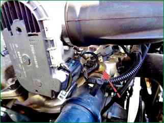
Throttle position sensors (TPS)
Two TPSs are used in an EAF system.
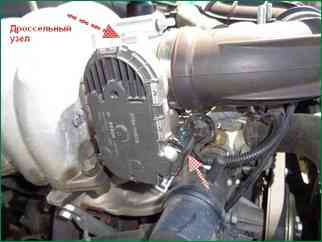
TPS are part of the electric throttle.
TPDZ is a potentiometric type resistor, one of the outputs of which is supplied with a reference voltage (5 V) from the controller, and the second one is grounded from the controller.
From the output connected to the moving contact of the potentiometer, the output signal of the TPS is supplied to the controller.
The controller controls the throttle position electrically according to the position of the accelerator pedal.
According to the readings of the TPS, the controller monitors the position of the throttle valve.
When the ignition is turned on, the controller sets the damper to the pre-start position, the degree of opening of which depends on the temperature of the coolant.
In the pre-start throttle position, the output signal of TPS 1 should be within 0.65-0.79 volts, the output of TPS 2 should be within 4.21-4.35 V.
If you do not start the engine and do not press the accelerator pedal within 15 seconds, the controller de-energizes the throttle pipe electric drive and the throttle valve is set to the position of 7-8% throttle opening.
In the de-energized state (LIMP HOME) of the electric throttle actuator, the output signal of TPS 1 is in the range of 0.80-0.85 volts, the output of TPS 2 is in the range of 4.15-4.20 V.
Next, if no action is taken within 15 seconds, the mode of checking ("learning") the 0-position of the throttle valve will come - full closing and opening of the throttle valve to the pre-start position and then the throttle actuator will again switch to the de-energized mode.
At any throttle position, the sum of the TPS 1 and TPS 2 signals must be equal to (5 ± 0.1) V.
If a malfunction occurs in the TPS circuits, the controller de-energizes the throttle actuator, stores its code in its memory and turns on the signaling device.
In this case, the throttle valve is set to the position of 7-8% throttle opening.
Electronic accelerator pedal (EPA)
Vehicles with an electronic throttle assembly use an electronic accelerator pedal that electrically transmits the accelerator pedal position signal to the controller.
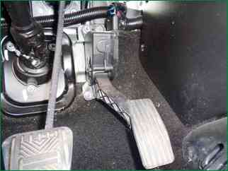
The electronic gas pedal is located on a bracket under the driver's right foot.
The electronic gas pedal uses two accelerator pedal position (APPS) sensors.
DPPAs are potentiometric type resistors powered by a 5V controller.
The DPPA is mechanically connected to the drive from the pedal lever.
Two independent springs between the pedal arm and the body provide a return force.
Receiving an analog electrical signal from the ESA, the controller generates a signal to control the throttle position.
The output voltage of the DPPA changes in proportion to the pressing of the accelerator pedal.
When the accelerator pedal is released, the DPPA 1 signal should be within 0.46-0.76 V, the DPPA 2 signal should be within 0.23-0.38 V.
When the accelerator pedal is fully depressed, the DPPA 1 signal should be within 2.80-3.10 V, the DPPA 2 signal should be within 1.40-1.55 V.
At any position of the accelerator pedal, the DPPA 1 signal must be twice as large as the DPPA 2 signal.
Coolant temperature sensor (DTOZH)
The sensor is installed in the engine coolant flow, on the outlet pipe of the engine water jacket.
The sensing element of the coolant temperature sensor is a thermistor, i.e. a resistor whose electrical resistance changes with temperature.
High temperature causes low resistance, and low coolant temperature causes high resistance.
The controller outputs 5 V to the coolant temperature sensor circuit.
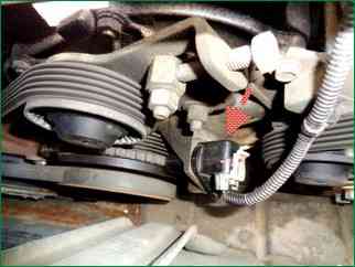
Knock sensor (DD)
installed on the cylinder block.
The piezoceramic sensing element DD generates an AC voltage signal, the amplitude and frequency of which correspond to the engine vibration parameters.
When detonation occurs, the amplitude of vibrations of a certain frequency increases. The controller at the same time corrects the ignition timing to dampen detonation.
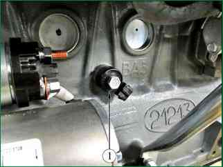
Control oxygen sensor (UDC)
The most effective reduction in the toxicity of exhaust gases of gasoline engines is achieved with a mass ratio of air and fuel in the mixture (14.5-14.6): 1.
This ratio is called stoichiometric.
At this air-fuel ratio, the catalytic converter most effectively reduces the amount of hydrocarbons, carbon monoxide and nitrogen oxides emitted with exhaust gases.
To optimize the composition of the exhaust gases in order to achieve the greatest efficiency of the catalyst, closed-loop fuel control with feedback on the presence of oxygen in the exhaust gases is used.
The controller calculates the duration of the injection pulse from parameters such as mass air flow, engine speed, coolant temperature, etc.
In order to correct the calculation of the injection pulse duration, information about the presence of oxygen in the exhaust gases, which is produced by the oxygen sensor
The UDC is installed on the pipe of the exhaust system. Its sensing element is located in the exhaust gas stream.
The UDC generates a voltage that varies in the range of 50-900 mV.
This output voltage depends on the presence or absence of oxygen in the exhaust gases and on the temperature of the UDC sensing element.
When the UDC is in a cold state, the output signal of the sensor is absent, since in this state its internal electrical resistance is very high - several MΩ.
As the sensor warms up, the resistance drops and the ability to generate an output signal appears.
For effective operation, the UDC must have a temperature of at least 300 ° C.
For quick warm-up after starting the engine, the UDC is equipped with an internal electric heating element controlled by the controller.
The duty cycle of the heater control pulse signals (the ratio of the duration of the on state to the pulse repetition period) depends on the UDC temperature and the engine operation mode.
If the sensor temperature is above 300°C, then at the moment of passing through the stoichiometry point, the sensor output signal switches between low level (50-200 mV) and high level (700-900 mV).
A low signal level corresponds to a lean mixture (the presence of oxygen), a high signal corresponds to a rich one (no oxygen).
Description of chain operation
The controller outputs a stable reference voltage of 1.6 V to the UDC circuit. When the UDC is not warmed up, the sensor output signal voltage is in the range of 1.2 -1.6 V.
As the sensor warms up, its internal resistance decreases and it begins to generate a fluctuating voltage outside this range.
By changing the voltage, the controller determines that the UDC has warmed up, and its output signal can be used to control fuel supply in closed loop mode.
During normal operation of the fuel supply system in closed loop mode, the output voltage of the UDC changes between low and high levels.
Poison oxygen sensor
UDC can be poisoned by the use of leaded gasoline or the use of room temperature curing sealants containing high levels of highly volatile silicone (silicon compounds) in assembly.
Silicone fumes can enter the crankcase ventilation system and be present during the combustion process. The presence of lead or silicon compounds in the exhaust gases can lead to failure of the UDC.
Malfunctions of the UDC circuits, a sensor defect, its poisoning or an unheated state can cause the signal voltage to stay in the range of 1.2-1.6 V for a long time.
At the same time, the corresponding fault code will be entered into the memory of the controller. The fuel supply will be controlled in an open loop.
If the controller receives a signal with a voltage indicating a prolonged lean condition, the corresponding fault code (low signal level of the oxygen sensor) is stored in its memory.
The cause of the malfunction may be a short circuit in the UDC output circuit to ground, a leak in the air intake system, or low fuel pressure.
If the controller receives a signal with a voltage indicating a long-term rich mixture condition, the corresponding fault code (high level of the oxygen sensor signal) is stored in its memory.
The cause of the malfunction may be a short circuit of the UDC output circuit to a voltage source or increased fuel pressure in the injector rail.
When oxygen sensor trouble codes occur, the controller controls the fuel supply in open loop mode.
Oxygen sensor maintenance
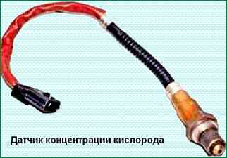
If the harness, pads or plugs of the oxygen sensor are damaged, the DC must be replaced.
Repair of the harness, socket or plugs is not allowed. For normal operation, the DC must communicate with atmospheric air.
Communication with atmospheric air is provided by the air gaps of the sensor wires.
Attempting to repair wires, pads or plugs can lead to a violation of communication with atmospheric air and a deterioration in the operation of the DC.
When servicing the DC, the following requirements must be observed:
Do not allow contact cleaner or other materials to come into contact with the sensor or harness pads. These materials can get into the DC and cause disruption.
In addition, damage to the insulation of the wires, leading to their exposure, is not allowed.
It is forbidden to strongly bend or twist the DC harness and the injection system wiring harness connected to it. This can disrupt the flow of atmospheric air into the recreation center.
To avoid a malfunction due to water ingress, it is necessary to prevent damage to the seal on the periphery of the control harness block.
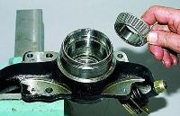
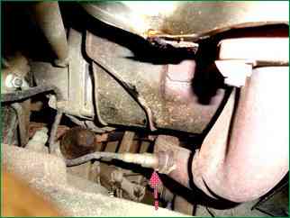
Diagnostic Oxygen Sensor (DOC)
A catalytic converter is used to reduce the content of hydrocarbons, carbon monoxide and nitrogen oxides in the exhaust gases.
The neutralizer oxidizes hydrocarbons and carbon monoxide, as a result of which they are converted into water vapor and carbon dioxide.
The neutralizer also recovers nitrogen from nitrogen oxides.
The controller monitors the redox properties of the converter by analyzing the signal from the diagnostic oxygen sensor installed after the converter.
DDC works on the same principle as UDC.
The UDC generates a signal indicating the presence of oxygen in the exhaust gases at the inlet to the converter.
The signal generated by the DDC indicates the presence of oxygen in the exhaust gases after the converter.
If the neutralizer is working properly, the readings of the DDC will differ significantly from the readings of the UDC.
The output signal of the heated diagnostic oxygen sensor, when operating in feedback mode, with a working converter in steady state, should be in the range from 590 to 750 mV and should not repeat the UDC signal.
If a malfunction occurs in the circuits or the diagnostic oxygen sensor itself, the controller stores its code in its memory and turns on the alarm, signaling a malfunction.
Maintenance requirements and the procedure for replacing the DDK do not differ from those described above for the UDC.
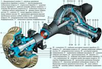
The vehicle speed sensor generates a pulse signal that informs the controller about the speed of the vehicle.
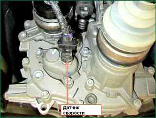
DSA set to input m transfer case shaft.
When the drive wheels rotate, the DSA generates 6 pulses per meter of vehicle movement. The controller determines the speed of the car by the frequency of the pulses.
In the event of a malfunction of the DSA circuits, the controller stores its code in its memory and turns on the signaling device.
Crankshaft position sensor
mounted on the cover of the camshaft drive at a distance of about 1 ± 0.4 mm from the top of the tooth of the drive disk mounted on the crankshaft of the engine.
The drive disc is integrated with the alternator drive pulley and is a gear wheel with 58 teeth in 6° increments and a "long" timing cavity formed by two missing teeth.
When the middle of the first tooth of the gear sector of the disk after the "long" cavity is aligned with the axis of the DPKV, the engine crankshaft is in position 114 ° (19 teeth) to the top dead center of the 1st and 4th cylinders.
When the master disk rotates, the magnetic flux in the magnetic circuit of the sensor changes, inducing alternating current voltage pulses in its winding.
The controller determines the position and frequency of rotation of the crankshaft by the number and frequency of these pulses and calculates the phase and duration of the pulses for controlling the injectors and the ignition coil.
The DPKV wires are protected from interference by a screen closed to ground.
If a malfunction occurs in the crankshaft position sensor circuit, the engine stops working, the controller stores the malfunction code in its memory and turns on the alarm.
Phase sensor
mounted on the tide of the cylinder head.
The principle of operation of the sensor is based on the Hall effect.
There is a special pin on the engine camshaft. When the pin passes against the end of the sensor, the sensor outputs a low-level voltage pulse (about 0 V) to the controller, which corresponds to the position of the piston of the 1st cylinder in the compression stroke.
The phase sensor signal is used by the controller to organize sequential fuel injection in accordance with the order of operation of the engine cylinders.
If a malfunction occurs in the circuits or the phase sensor itself, the controller stores its code in its memory and turns on the signaling device.
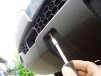
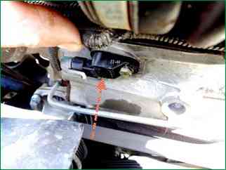
Brake light switch
included in the brake pedal assembly and is designed to provide appropriate signals to the ECM when the driver presses / releases the brake pedal.
In throttle-by-wire (E-gas) control systems, the brake pedal switch signals play an important role because they are used by the safety function of the ECM software.
For this reason, it is very important to ensure that the brake light switch is always in working order.
In the event of a discrepancy between its functional characteristic of switching, for example, in case of spontaneous changes in the values of the adjustments specified in the instructions (due to vibrations of the brake pedal, wear of the switch and pedal block), the car engine may switch to emergency operation with a forcibly reduced power.
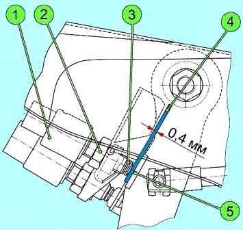
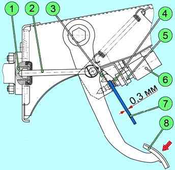
The value of the adjustment gap of the switch should be within 0.4 ± 0.1 mm (figure).
The brake light switch has two sets of contacts.
The first group of contacts switches the voltage from terminal "15" of the ignition switch, the second - the voltage from terminal "30" of the ignition switch, which is supplied to the stop lamp. Both of these signals are sent to the ECM.
When the brake pedal is released, the contacts of the first group must be normally closed, and the contacts of the second group must be normally open.
If the brake light switch malfunctions, the controller stores its code in its memory and turns on the warning device.
The fault code is also entered when the th adjustment of the gap (0.4 ± 0.1 mm) between the head of the movable rod 3 and the switch body 1
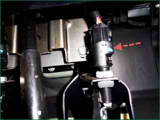
Clutch position switch
Included in the clutch pedal assembly and is designed to signal the ECM that the clutch pedal is depressed.
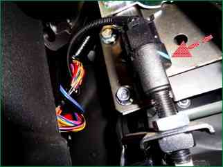
The switch has one group of contacts that switch voltage from terminal "15" of the ignition switch.
When the clutch pedal is depressed, the contacts are open.
The clutch pedal position switch signal is used by the ECM software to improve the vehicle's driving performance.
In the event of a malfunction of the SSPS, the controller stores its code in its memory and turns on the signaling device.
The value of the adjusting gap should be within 0.3±0.1 mm (picture).