The water pump is a centrifugal type, with an electromagnetic fan drive clutch, mounted on the chain cover, the coolant is supplied by the pump to the cylinder block
The tightness of the pump is ensured by a self-clamping mechanical seal 7, which is pressed into the housing 6 of the water pump and onto the bearing shaft 11.
The coolant penetrating through the seal does not enter the bearing, but flows through the hole into the drainage cavity 9, closed with a plug
The liquid accumulating in the drainage cavity during engine operation gradually evaporates through holes 10 and 4.
The steam that enters through the seal evaporates into the atmosphere through opening 4.
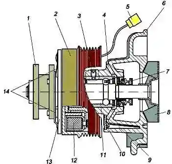
In operation, it is necessary to monitor the cleanliness of holes 4 and 10, and, to prevent premature failure of the bearing, during TO-2, the holes must be cleaned of dirt.
The presence of a constant leak from the control hole 10 of the drainage cavity indicates a loss of tightness of the seal and the need to replace the water pump.
Bearing 11 is kept from moving in the water pump housing by retainer 3, which is screwed up to the stop and centered.
The bearing with two protective seals is filled with grease at the factory and does not require relubrication during operation.
A stamped steel impeller 8 is pressed onto the bearing shaft.
At the front end of the water pump housing, an electromagnet coil 12 of the electromagnetic clutch is fixedly mounted on the holder.
The hub 1 of the fan mounting is mounted on the bearing shaft of the water pump on a ball bearing.
In the absence of voltage on the electromagnet, the hub 1, together with the driven disk 13, is disconnected from the pulley 2 and rotates freely at a low angular speed.
When voltage is applied to the clutch electromagnet, the driven disk 13, overcoming the force of the leaf springs 14, is attracted to the pulley 2 and the fan hub begins to rotate together with the pulley and the water pump bearing shaft.
When the voltage is removed from the clutch electromagnet, the leaf springs 14 move the disc 13 away from the pulley 2, separating the hub and the pulley.
The connection of the electromagnetic clutch to the vehicle's electrical system is carried out using connector 5.
The clutch solenoid is energized by a signal from the control unit through a relay when the coolant temperature rises above plus 93 ± 2 °C, and it turns off when it drops below plus 91 ± 2 °C.
Main parameters of the electromagnetic clutch:
- 1. Supply voltage—10.8...15V.
- 2. Consumed electrical power - no more than 50 W.
- 3. The transmitted torque at a voltage of 12 V is at least 20 Nm (2 kgf m).
- 4. The minimum operating voltage is 10 V.
- 5. The transmitted torque at minimum voltage is not less than 11 Nm (1.1 kgf m).
- 6. The gap between the driven disk and the pulley is 0.2. . .0.5 mm.
The water pump with electromagnetic clutch is a non-repairable product.
If the water pump or the electromagnetic clutch fails, the entire assembly must be replaced.
The drive of the water pump and the generator (without the power steering pump) is carried out by a V-ribbed belt 6RK 1275 from the crankshaft pulley.
The gear ratio of the water pump drive is 1.11.
The belt tension is carried out by an automatic tensioner, which provides the necessary belt tension when it is stretched and damping (damping) the oscillations that occur in the drive.
During operation, the tensioner does not require maintenance and adjustment.
In addition to eliminating the need to adjust the belt tension, the use of an automatic tensioner allows you to increase the life of the accessory drive belt and the life of the bearings of the water pump, generator and tensioner roller.
Replacing the engine coolant pump ZMZ-40524
We drain the liquid from the cooling system (see the article - Replacing the coolant).
For a better approach, remove the radiator (see the article - Removing the radiator).
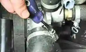
Loosen the clamp of the radiator outlet hose
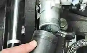
Remove the outlet hose from the water pump nozzle
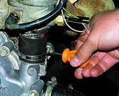
Loosen the hose clamp to the thermostat
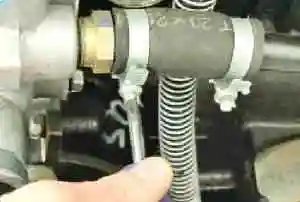
Loosen the hose clamp of the coolant intake pipe
And remove the hoses from the nozzles of the water pump
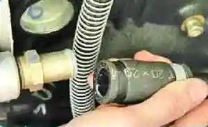
Remove the auxiliary drive belt (see article - Replacing the belt)
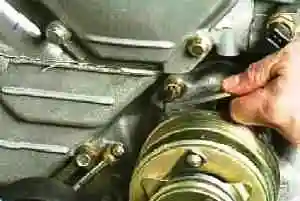
We unscrew the bolt of the water pump housing
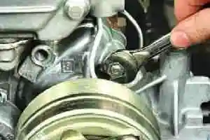
Unscrew the top nut
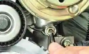
Unscrew the bottom bolt
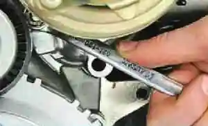
Unscrew the bottom nut of the water pump
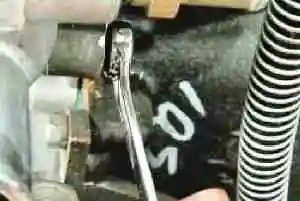
Unscrew the pump mounting bolt from the exhaust manifold
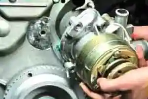
Remove the water pump assembly with the electromagnetic clutch of the radiator fan drive of the engine cooling system
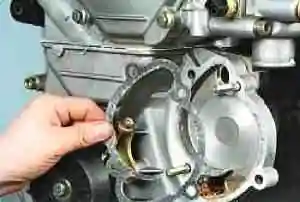
Remove the gasket and clean the surface of the remnants of the gasket
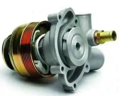
The water pump is sold with an electromagnetic clutch
Install parts in reverse order.
Before installing the pump, sealant must be applied to mating surfaces.
Fill coolant.
Checking the electromagnetic clutch of the water pump
Check the rotation of the fan mount hub. The rotation of the hub must be free.
If the driven disk touches the end of the pulley, the hub bearing seizes or the hub bearing has large play, replace the water pump assembly with the clutch.
To check the maximum transmitted torque by the clutch, attach the water pump to the pulley and, using a torque wrench, set the moment at which the hub will rotate relative to the pulley when the supply voltage to the clutch is 10 V and 12 V.
The moment must be at least 1.1 kgf m and 2.0 kgf m, respectively.


