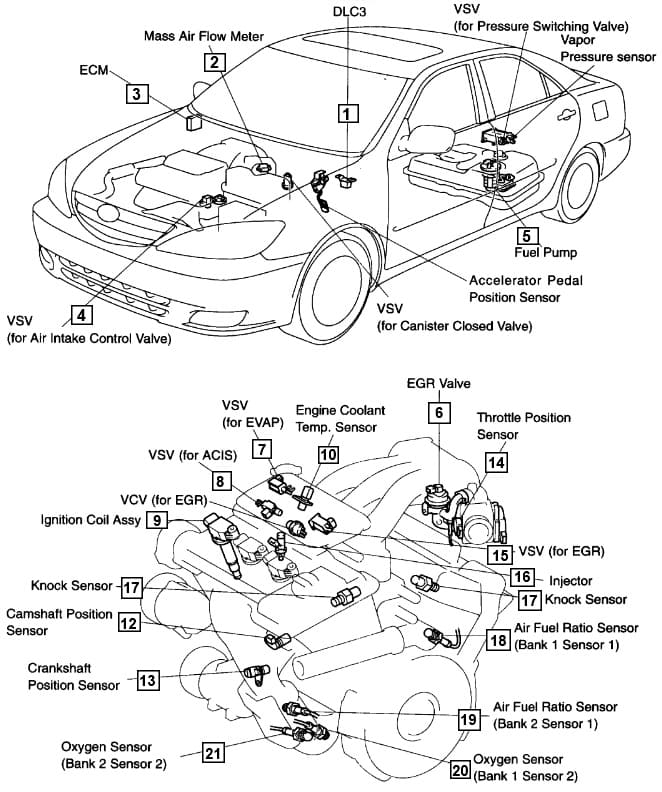
The main elements of the 1MZ-FE engine control system are presented in the table
Their location on the car, see fig. 1.
The electronic engine control system consists of sensors for engine and vehicle condition parameters, a controller and actuators.
The controller is the central unit of the engine control system.
It receives information from sensors and controls the actuators, ensuring optimal engine operation at a given level of vehicle performance.
The controller controls actuators such as fuel injectors, motorized throttle, ignition coil, oxygen sensor heater, canister purge valve, and various relays.
The controller controls the on and off of the main relay (ignition relay), through which the supply voltage from the battery is supplied to the elements of the system (except for the electric fuel pump, electric fan, control unit and APS status indicator).
The controller turns on the main relay when the ignition is turned on.
When the ignition is turned off, the controller delays turning off the main relay for the time necessary to prepare for the next turn on (completion of calculations, setting the throttle to the position before starting the engine).
When the ignition is turned on, the controller, in addition to performing the functions mentioned above, exchanges information with the APS (if the immobilization function is enabled).
If the exchange determines that access to the vehicle is allowed, then the controller continues to perform engine control functions.
Otherwise, the engine will be blocked.
The controller also performs a system diagnostic function.
It determines the presence of malfunctions of system elements, turns on the alarm and stores codes in its memory that indicate the nature of the malfunction and help the mechanic to carry out repairs.

Characteristics of the control system
Engine ECM - 32-bit ECM (previous version uses 16-bit ECM)
Air flow sensor - hot-wire type
Crank angle sensor (number of rotor teeth) - inductive type (36-2)
Camshaft position sensor (number of rotor teeth) - inductive type (3)
Throttle position sensor - linear type
Fuel pedal position sensor - linear type
Knock sensor - built-in piezoelectric
Oxygen concentration sensor - with heating element
Oxygen concentration sensor (row 1, sensor 2), (row 2, sensor 2) - with heating element
Fuel injector - 12 holes (previous version used with 4 holes)


