Cylinder head disassembly
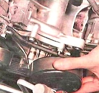
Remove the oil pressure sensor
Remove the coolant temperature sensor.
Remove the camshaft position sensor by unscrewing the mounting bolt.
Remove the pushrods.
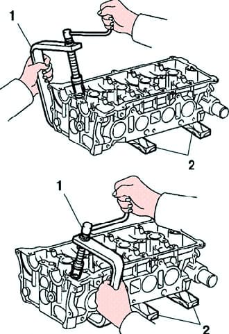
Remove the valves.
Use the special tool 09202-70020 (09202-00010) to compress the valve spring and remove the two cotters.
Remove the spring plate, spring and valve (fig. 1).
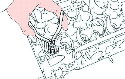
Using pliers, remove the valve stem seals.
Remove the valve spring seat.
Remove the cylinder head bolts
Cylinder head assembly
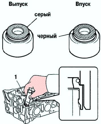
Using the special tool 09201-41020, install new valve stem seals.
The intake valve stem seals are painted black and the exhaust valve stem seals are gray (fig. 3).
Install the parts in the following order:
- 1 – valve;
- 2 – spring seat;
- 3 - spring;
- 4 - spring plate.
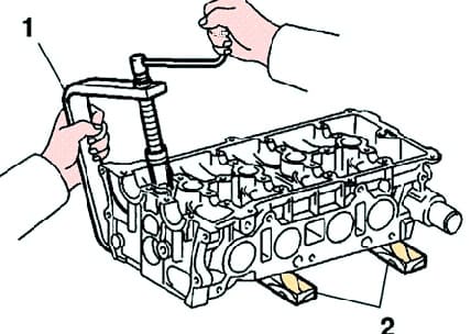
Using the special tool 09202-70020, compress the valve spring and install two cotters around the valve stem (fig. 4).
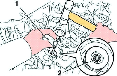
Using a plastic-headed hammer and the stem of an unused valve wrapped in insulating tape, hit the end of the valve stem to ensure that the valve is securely fixed with crackers (fig. 5).
Install the valve lifters and make sure the lifters turn freely.
Install the camshaft position sensor with a tightening torque of 9 Nm.
Install the coolant temperature sensor with a tightening torque of 20 Nm.
Install the oil pressure switch by applying sealant to 2-3 threads with a tightening torque of 13 Nm.


