1MZ-FE engine head repair
Before removing the valves, remove the tappets and shims
Store tappets and shims in the order in which they were installed
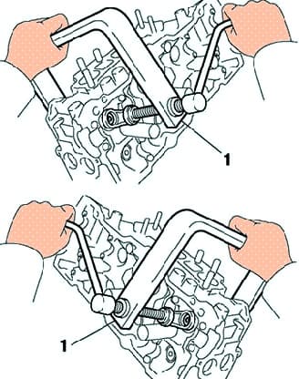
Using the special tool, compress the valve spring and remove the two cotters (fig. 1).
Remove the valve spring cap, valve spring, valve and spring seat.
Using pliers, remove the valve stem seals.
Replacing the valve and guide sleeve
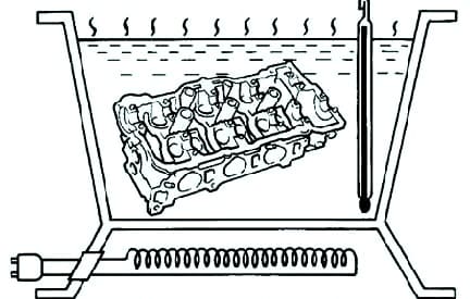
Slowly heat the cylinder head in a water bath to a temperature of 80–100°C (Fig. 2).
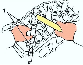
Using a drift and a hammer, press out the guide bushing (fig. 3).
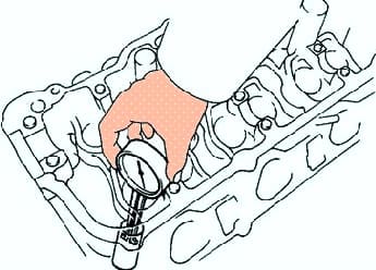
Measure the diameter of the bore for the guide bushing in the cylinder head housing with a bore gauge (Fig. 4).
Choose a new size for the outside diameter of the valve guide (standard or overhaul +0.05 mm).
If the diameter of the hole for the guide in the head housing exceeds 10.313 mm, then bore the hole for the guide sleeve to a repair (+0.05 mm) diameter of 10.345–10.363 mm.
If the diameter of the hole for the guide in the head housing exceeds the repair size, then replace the cylinder head.
Select the bushings of the inlet and outlet valves depending on the diameters of the holes for the guides.
Use a standard bushing if the guide hole diameter is 10.295-10.313mm.
Use repair (+0.05mm) bushing if guide hole diameter is 10.345-10.363mm.
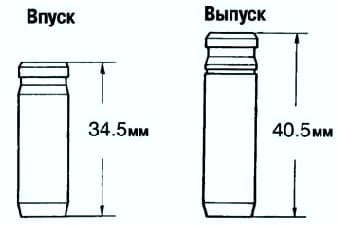
Intake and exhaust valve guides differ in length (fig. 5).
Length of guide sleeves:
- - inlet valves - 34.5 mm;
- - exhaust valves - 40.5 mm.
Heat the cylinder head in a water bath to a temperature of 80–100 °C.
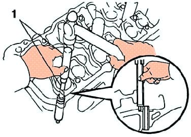
Using a drift and hammer, install the new valve guide so that it protrudes from the block head by the appropriate amount (fig. 6).
Guide bush protrusion:
- - inlet valve - 11.5–11.3 mm;
- - exhaust valve - 8.9–9.3 mm.
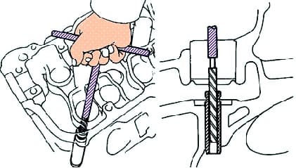
Using a 5.5mm reamer, ream the inner hole of the guide to provide the nominal clearance between the guide and the valve stem (fig. 7)
Checking and lapping the valves
Sand the valves until all carbon deposits and scratches are removed.
Make sure you have The valve's mouth chamfer forms an angle of 44.5° relative to the plane perpendicular to the axis of the rod.
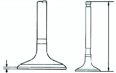
Check the thickness of the cylindrical part of the valve disc (fig. 8).
Standard plate thickness is 1.0 mm.
If the thickness of the cylindrical part of the valve disc is less than the minimum allowable value, replace the valve.
Check overall valve length
If the overall length is less than the minimum, replace the valve.
Nominal length:
- - inlet valve - 95.45 mm;
- - exhaust valve - 95.40 mm.
Minimum overall length:
- - inlet valve - 94.95 mm;
- - exhaust valve - 94.90 mm.
Check the condition of the valve faces for wear.
If the valve end is worn, regrind the end or replace the valve.
After sanding, check the overall valve length.
Then, use a 45° carbide cutter to grind the valve seats, removing only the minimum amount of metal to clean the seat bevels.
Check that the valve is seated correctly.
Apply a thin coat of white to the bevel of the valve.
Push the valve face against the seat, but do not rotate the valve.
Then remove the valve and inspect the valve seat and bevel.
If the paint remains around the entire circumference (360°) of the valve chamfer, then the valve is concentric.
If not, replace the valve.
If the paint appears around the entire circumference (360°) of the valve seat, the valve guide (sleeve) and valve seat are concentric.
Otherwise, regrind the bevel.
Make sure the contact patch is in the middle of the valve face and is 1.0-1.4mm wide.
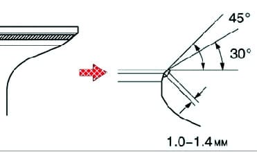
If not, adjust the chamfer so that the contact patch is not too high on the valve chamfer.
To regrind the seat, use 30° and 45° taper cutters (fig. 10)
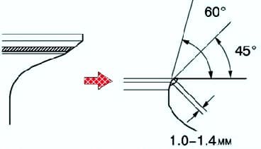
If the contact patch is too low on the valve face, use 75° and 45° taper cutters to regrind the seat (fig. 11).
Lap the valve and valve seat by hand using abrasive paste.
After lapping, clean the valve and valve seat.
Valve spring check
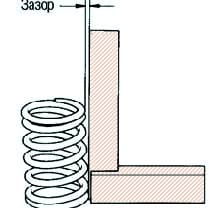
Using a metal square (90°), check that the valve spring is not perpendicular, as shown in Figure 12.
The maximum allowable non-perpendicularity is 2.0 mm
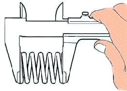
Measure the free length of the spring with a caliper (Fig. 13).
The length of the valve spring is 45.50 mm.
If the spring length is out of specification, replace the valve spring.
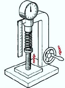
With a spring tester, measure the force required to compress the spring to the installation length (fig. 14).
The spring force with a length of 33.8 mm is 186–206 N.
If the force is out of range, replace the valve spring
Checking the valve tappet
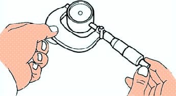
Measure the diameter of the valve lifter with a micrometer (fig. 15).
Pusher diameter - 30.968–30.976 mm.
Calculate the oil clearance.
Subtracte value of the pusher diameter from the value of the tappet bore diameter in the head body and determine the clearance.
Oil clearance:
- - standard - 0.024–0.050 mm;
- - maximum - 0.07 mm.
If the gap exceeds the maximum allowable, replace the pushrod. If necessary, replace the cylinder head.


