Put the car on a two-post lift.
Disconnect the battery.
Remove the battery.
Remove the right front wheel.
Remove the right front fender liner.
Remove the top engine covers.
Install the tools (Mot. 1453) and (Mot. 1453-01) with holding straps.

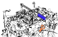
Remove the right side reinforcement of the radiator frame cross member and the lower reaction rod (Fig. 1)
Disconnect the connectors, disconnect the hood latch cable.

Remove the holder (fig. 2)
Unscrew the mounting bolt and remove the front bumper (Fig. 2)
Disconnect the washer tubes.

Unscrew the bolts securing the front panel of the body (Fig. 3)
Remove the front body panel.
Remove the right front wheel drive shaft.

Install tool (Mot. 1672) with fastening straps (fig. 4)

Mark the position of the pendulum support relative to the body (fig. 5).
Remove the pendulum support.
Take care not to deform the air conditioning piping.
Remove the accessory drive belt.

Remove the air cleaner outlet duct, throttle body and wiring harness from the lifting lug (fig.6)

Remove the canister purge solenoid valve (fig. 7)

Unscrew the nut, pull the electric water pump mounting post and move it to the side (fig. 8)

Remove the plug from the hole for the TDC lock (Fig. 9)
Remove the camshaft plugs (Fig. 10)

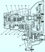
When setting the valve timing, you need to understand the meaning of the engine design.
The crankshaft pulley may or may not be keyed and.
And the camshaft pulleys are without keys.
The meaning of this design is to first install the belt and make it the correct tension, and then tighten the pulleys.
The shafts themselves (crankshaft and camshafts) are locked in the TDC position.
The crankshaft is blocked through a special hole using a pin-bolt.
Distributing bolts are blocked from turning by means of a tool through holes closed with plugs.
At opposite ends of the camshafts there is an eccentric slot into which the tool is installed.
The fixture is installed when the camshafts are slotted down relative to the center.
Before tensioning the belt, the camshaft pulleys are not tightened and can turn on the shafts, while the shafts themselves are blocked from turning.
After the belt has been installed and tensioned, tighten the bolts securing the crankshaft pulleys and camshafts.
First valve timing

Turn the engine clockwise (when viewed from the timing end) so that the camshaft grooves are pointing down and almost horizontal, as shown in Figure 11.
Insert the TDC lock (Mot. 1054) so that it is between the balancing hole and the crankshaft locking slot (fig. 12).

Rotate the crankshaft in the same direction until the TDC lock (Mot. 1054) is in the locking groove of the crankshaft.

In the installation position, the grooves of the camshafts are horizontal and axially shifted down, as shown in Figure 13.
Remove the TDC lock.

Remove the flywheel guard and crankshaft pulley by blocking the engine flywheel with a screwdriver (fig. 14).
Install the top dead center lock (Mot 1054).

Remove the upper and lower timing covers (fig. 15)

Remove the heat shield (fig. 16)

Loosen the timing belt by unscrewing the tensioner axle nut (Fig. 17).
Remove the idler pulley, timing belt and crankshaft sprocket.
Never turn the engine crankshaft in the opposite direction of rotation
Second camshaft setting
Check that the inlet camshaft dephaser ring gear is securely locked (the ring cannot be turned left or right)

Mount the gear (Mot. 1509-01) to the special tool (Mot. 1509).

Slide the tool spacer (Mot. 1509-01) onto the pin (fig. 19)

Install the top bolt, placing a spacer (Mot. 1509-01) between the tool and the cylinder head cover, finally tighten the bolt and collar nut.
Move the gears of tool (Mot. 1509) to the camshaft pulleys.

Tighten the nuts securing the toothed pulleys (80 Nm).
Remove the plug of the inlet camshaft dephaser (fig. 21).
Remove the intake camshaft dephaser mounting bolt.
Remove the exhaust camshaft sprocket nut and tool (Mot. 1509).
Remove the camshaft pulleys.
If necessary, unscrew the stud and nut.

Install tool (Mot. 1509) with gears (Mot 1509-01).
Tighten the bolt and collar nut.
Move the tool gears until they touch the camshaft pulleys.
Tighten the toothed pulley studs (80 Nm) (fig. 22).
Unscrew the nuts securing the camshaft pulleys.
Remove tool (Mot. 1509) and camshaft pulleys.
Install the pre-greased camshaft pulleys using the old nuts.
Using the tool (Mot. 799-01), tighten the nuts to the required torque of 15 Nm.

When replacing the timing belt, be sure to replace the crankshaft pulley, bypass and idler rollers, and the timing and accessory drive belts.
Install the offset slots horizontally downwards as shown above by turning the camshafts using tool (Mot. 799-01).
Fix tool (Mot. 1496) on the ends of the camshafts (fig. 23).
Remove the exhaust camshaft sprocket nut and the intake camshaft dephaser pulley bolt.
Remove the nuts securing the camshaft pulleys.
Make sure the crankshaft is locked.

The groove of the crankshaft must be between the two ribs (fig. 24)
Install the tension roller, placing its protrusion in the groove (fig. 25).

Install the crankshaft sprocket, timing belt and idler.
Install the crankshaft sprocket, timing belt and idler.
Tighten the bypass roller bolt to the required torque (50 Nm).
Checking belt tension

Do not turn the idler counterclockwise.
Align the marks on the idler roller with a 6mm hex wrench (fig. 26).
Tighten the tension roller axle nut to the required torque (7 Nm).
Install tools (Mot. 1509) with gears and (Mot. 1509-01) to lock the camshaft pulleys.
Tighten the bolt and collar nut.
Tighten the nuts securing the toothed pulleys until they touch the camshaft pulleys.
Torque tighten:
- - nuts for the studs of the toothed pulleys (80 Nm);
- - the old bolt for fastening the phase regulator of the intake camshaft (30 Nm);
- - the nut of the exhaust camshaft pulley (30 Nm).
Remove tool (Mot. 1509) with tool (Mot. 1509-01).
Install tool (Mot. 1509) to lock the camshaft pulleys.
Tighten the bolt and collar nut.

Tighten the nuts securing the toothed pulleys until they touch the camshaft pulleys.
Torque tighten:
- - nuts for the studs of the toothed pulleys (80 Nm);
- - nuts for fastening the toothed pulleys of the intake and exhaust camshafts (30 Nm).
Remove tool (Mot. 1509) with tool (Mot. 1509-01).
Mark with a pencil the position of the camshaft pulleys relative to the camshaft bearing caps.
Align the TDC lock (Mot. 1054) and the camshaft locking tool (Mot. 1496).
Turn the crankshaft two turns clockwise (when viewed from the timing end).
Installation
Install the lower and upper timing covers.
Be sure to replace the mounting bolt and crankshaft pulley.
Lock the engine flywheel with a large screwdriver.
Tighten the crankshaft pulley bolt to a torque (40 Nm, then tighten by 110 ° + 10 °).
To prevent damage to the crankshaft pulley, do not start the engine unless the accessory drive belt is installed.
Install the accessory drive belt.
Install the top dead center plug with a small amount of sealant.
Install new inlet camshaft and exhaust camshaft plugs.
The rest of the components are installed in the reverse order of removal.
")
")
")
")
")
")