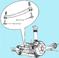
Put on all tappets, valves and springs marks corresponding to their location in the cylinder head so that during assembly, they do not change their original location
Remove the valve spring support.
Remove the valve spring.
Remove the valve.
Remove the valve stem seal.
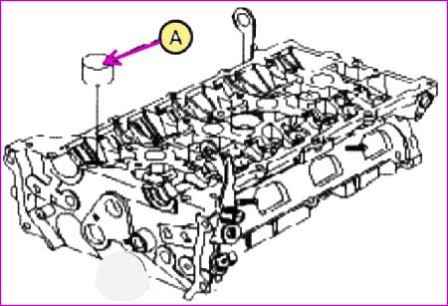
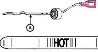
Remove the tappets (A) from the cylinder head
Remove the valves. For this:
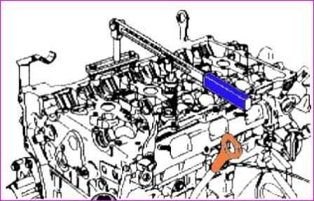
Using special tools (09222-3K000, 09222-ZK10), compress the spring and remove the valve cotters, as shown in the figure
Checking the technical condition of the cylinder head parts
Cylinder head
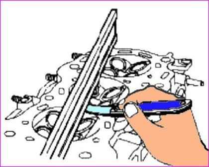
Check the flatness of the cylinder head-to-block connector surface.
For this, you need to use a special ruler and a set of probes.
Placing the ruler in the planes indicated in the figure, measure the non-flatness of the connector surface with probes.
Standard amount of surface non-flatness; less than 0.05 mm.
Check the combustion chambers, intake and exhaust ducts, and the cylinder block mating surface for damage.
If any defects are found, replace the head assembly.
Valves, tappets, guide bushings and valve springs
Check the technical condition of the guide bushings and valves.
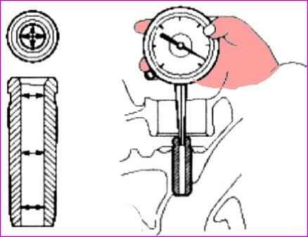
Using a bore gauge, measure the inside diameter of the valve guide as shown.
Standard internal diameter value; 5.500 – 5.512 mm.
Using a micrometer, measure the outside diameter of the valve stem as shown.
Standard valve outer diameter: 5.465 - 5.480 mm (inlet), 5.458 - 5.470 mm (outlet).
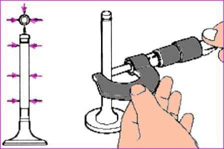
The difference between the inner diameter of the guide sleeve and the outer diameter of the valve stem is the gap between the valve and the sleeve.
If the gap is greater than the maximum allowable value, it is necessary to replace the valve assembly with the sleeve.
Check the technical condition of the valves.
Check the angle of sharpening of the working chamfer of the valve head.
Check the valve surface for excessive wear. If any defects are found, replace the valve with a new one.
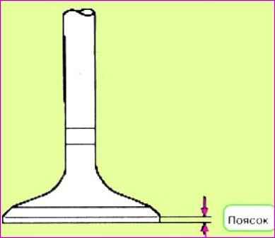
Check the thickness of the valve head band.
If the thickness of the valve head band is less than acceptable, it is necessary to replace the valve with a new one.
Standard belt thickness: 1.02 mm (inlet), 1.09 mm (outlet).
Measure the overall length of the valve. Standard valve length: 113.18mm (inlet), 105.84mm (outlet).
Check the technical condition of the valve seats.
Check that the valve fits snugly against the seat, around its entire circumference. Replace valve seats if necessary.
Before restoring the valve seats, it is necessary to check the technical condition of the valve guides.
If any defects are found, it is necessary to replace the sleeve, and then rebuild the seat.
The thickness of the contact surface of the seat with the valve must correspond to the standard value.
Check the technical condition of the valve springs.
Using a steel square, measure the amount of deflection from the vertical axis of the spring.
Vertical deviation tolerance: 1.5˚. maximum permissible deviation: 3˚.
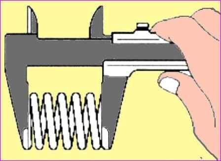
Using a caliper, measure the free length of the spring. Standard spring length: 47.44 mm.
If the free length of the spring is not within the standard value, the spring must be replaced.
Using a micrometer, measure the outside diameter of the tappet. Standard value: 31.964 - 31.980 mm.
Using a compass, measure the inner diameter of the tappet hole in the cylinder head, value: 32.000 - 32.025 mm.
Subtract from the value of the inner diameter under the pusher the measurement of the outer diameter to determine the gap, value: 0.020 - 0.061 mm. Limit value 0.07 mm.
Camshaft
Using a micrometer, measure the height of the camshaft lobes.
Standard cam height: 44.10 - 44.30mm (inlet), 44.90 - 45.10mm (outlet).
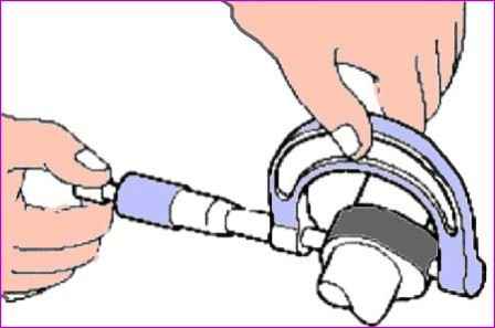
NOTE:
If the camshaft lobe height is less than the minimum, the camshaft assembly must be replaced.
Check the clearance in the camshaft bearings.
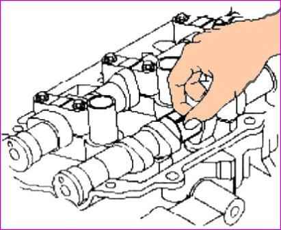
Clean and rinse the bearing caps and camshaft journals.
Install the camshafts in the cylinder head.
Place special plastic gauges on the camshaft journals as shown.
Install the camshaft bearing caps.
Do not rotate the camshaft.
Remove the camshaft bearing caps.
Measure the thickness of the plastic gauge (a scale is included with the plastic gauge set). From this, determine the amount of clearance in the bearings.
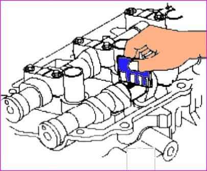
Standard liner gap:
- #1: 0.022 - 0.057mm, #2, 3, 4, 5: 0.045 - 0.082 (inlet),
- #1: 0 - 0.032mm, #2, 3, 4, 5: 0.045 - 0.082.
Max:
#1: 0.09mm, #2, 3, 4, 5: 0.12mm (inlet); 0.12(release).
If the clearance in the bearings exceeds the allowable limit, the camshaft must be replaced.
If necessary, replace bearing caps or cylinder head assembly.
Remove completely plastic gauges.
Remove the camshafts.
Measure the camshaft end play.
Install camshafts.
Using a dial gauge, measure the end play by moving the camshaft forward / backward.
Standard camshaft end play: 0.04 - 0.16 mm. Maximum allowable: 0.24 mm.
If the axial clearance exceeds the maximum allowable value, the camshaft must be replaced.
If necessary, replace the camshaft bearing caps and cylinder head assembly.
Remove the camshafts.
Exhaust camshaft bearing
Check the cylinder head bore mark.
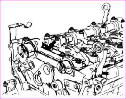
Label location:
|
Class |
Label |
Internal hole diameter prom camshaft No. 1, mm |
|---|---|---|
|
a |
A |
40,000 – 40,008 |
|
b |
B |
40.008 – 4.016 |
|
c |
C |
40.016 – 40.024 |
Select a bearing class such as cylinder heads as shown in the table.
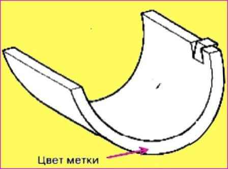
Label location:
|
Class |
Label |
Thickness liner, mm |
|---|---|---|
|
a (A) |
С (green) |
1,996 – 2,000 |
|
b (B) |
B (no color) |
2,000 – 2,004 |
|
c (C) |
A (black) |
2.004 – 2.008 |
Oil clearance: 0 - 0.032mm.
Mechanism for changing the valve timing assembly (phase shifter)
Check the technical condition of the variable valve timing assembly.
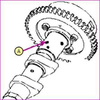
Check and make sure that the mechanism does not rotate.
Wrap all parts of the mechanism with vinyl tape, except for the one shown in the picture below
Wrap a special air gun as well, then apply a pressure of 150 kPa to the hole on the camshaft (when performing this operation, remove the locking pin).
Assembly
After splashing engine oil, wipe the surfaces with a rag.
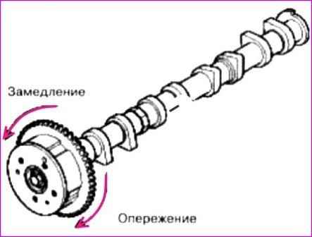
While performing the above operation, manually rotate the phase shifter assembly in the direction of advance (the direction is indicated by the arrow in the figure above).
When compressed air is supplied, the phase shifter must be moved forward without effort, by hand.
Except for the position when the stop pin reaches the maximum deflection in the direction of delay.
After that, rotate the phase shifter back.
Check the smoothness of its movement, excluding jamming, the range of movement of the phase shifter is 22.5˚ (inlet), 20˚ (exhaust).
Turn the phase shifter assembly by hand and fix it in the late limit position.
Install valves.
Install the lower valve spring supports.
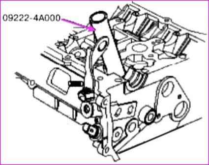
Using the special tool (09222-4А000), install the valve stem seal.
Do not reuse the valve stem seal.
Incorrect installation of the valve stem seal may result in engine oil leaking through the valve guide.
Install the valve, valve spring and upper spring seat.
Using the special tool (09222-ЗК000, 09222-3К100), compress the valve spring and install the valve crackers.
After installation, make sure is that crackers are installed properly.
The valve spring must be installed so that the polished part of the coils is directed upwards (toward the upper support).
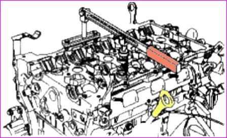
Put a few light blows with a wooden hammer on the valve stems to make sure that the crackers have fixed the valves properly.
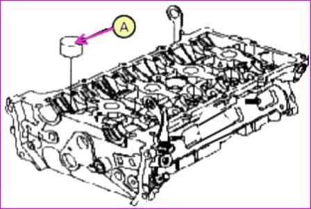
Install valve tappets "A".
Check and make sure that the pusher moves smoothly


