Removing and installing the casing and clutch disc (K4J and K4M engines)
Remove the gearbox
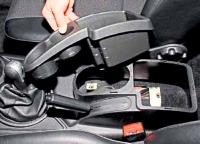
Install the retainer (Mot582-01) (fig. 1).

Remove the clutch cover bolts.
Remove the clutch disc.
Use a vacuum cleaner or a clean cloth to remove dust from the clutch cover.
Do not use compressed air as breathing dust containing asbestos is harmful to your health.
Check the condition of the friction surface of the flywheel for cracks, burn marks and surface wear.
Check the condition of the friction linings of the clutch disc and if there are traces of oil or mechanical damage on them, replace the clutch disc.
Clean the transmission input shaft splines and mount the assembly without lubrication.
Installation
Install the clutch disc.

Center the driven disc using the mandrel (Emb1518) (fig. 2).
Tighten the fastening bolts crosswise in several steps.
Tighten to torque (20 Nm) the clutch cover mounting bolts (K4J and K4M engines).
Removing and installing the clutch basket and clutch disc (F4R engine)
Remove the gearbox.

Install the retainer (Mot582-01) (fig. 3).
Remove the clutch cover bolts.
Remove the clutch disc.
Use a vacuum cleaner or a clean cloth to remove dust from the clutch cover.
Do not use compressed air as breathing dust containing asbestos is harmful to your health.
Check the condition of the friction surface of the flywheel for cracks, burn marks and surface wear.
Check the condition of the friction linings of the clutch disc and if there are traces of oil or mechanical damage on them, replace the clutch disc.

If you have an automatic gap adjustment system, compress the petals of the clutch cover pressure spring using the tool (Emb1604) (Fig. 4).
Installation

Place the fixture base (Emb. 1604) in the vise (fig. 5).

Install the clutch cover on the base, then the clutch release bearing and nut (fig. 6).

Turn the nut all the way down (fig. 7).

Install the locking wheel pliers in the location shown in Figure 8. with the arrow.

Compress the spring (fig. 9).
Loosen the nut completely (with the springs compressed).
Relieve the clutch cover.

Remove the clutch cover from the base, while making sure that the springs are compressed (fig. 10).
Clean the transmission input shaft splines and mount the assembly without lubrication.
Degrease the surface of the flywheel under the clutch disc.

Install the clutch disc.
The side of the hub with the smaller diameter should face the flywheel, as shown in Figure 11.
To center the clutch disc, use the plastic drift supplied with the clutch repair kit (Emb1518).

Mount the clutch cover to the flywheel (fig. 12).
Alternately tighten the clutch cover bolts in several steps (12 Nm).
")
")
")
")
")
")