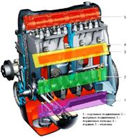
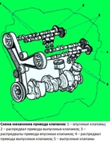
To improve the filling of cylinders with a fuel mixture in all modes, 2.0 liter engines. equipped with inlet camshaft dephaser
Shifting the closing timing of the intake valves optimizes the filling of the cylinders with the fuel mixture depending on the speed of the crankshaft.
The result is increased torque at medium loads and power at high engine speeds.
At a high engine speed, closing the intake valves later provides an additional portion of the fuel mixture due to the high speed of the mixture.
On the contrary, at a low speed, the inertia of the mixture is small.
Earlier closing of the exhaust valves is therefore desirable to avoid underfilling of the cylinders and loss of torque due to the displacement of some of the fresh mixture.
The higher the engine speed, the later the intake valves should close.
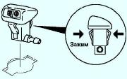
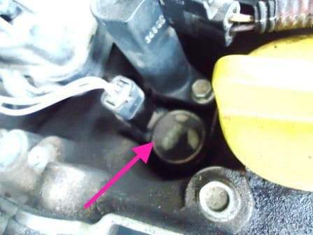
The phase control is either disabled or controlled by the injection computer through a solenoid valve mounted on the cylinder head cover (see fig. 2.).
Solenoid valve and high voltage coil are fixed with one bolt (fig. 3)
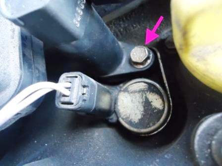
When the engine speed is between 1500-4300 rpm, the ECU supplies voltage to the solenoid valve.
After exceeding 4300 rpm, the power supply to the solenoid valve stops.
At the same time, the position of the phase regulator mechanism contributes to filling the cylinders at a high crankshaft speed.
In this position, the locking plunger blocks the mechanism.
Note. At a speed of up to 1500 rpm, the solenoid valve is not energized.
The mechanism is blocked by a plunger.
From the moment power is applied to the solenoid valve at a crankshaft speed of more than 1500 rpm, under the influence of oil pressure, the locking plunger moves away and releases the mechanism.
In the initial position, the solenoid valve (Fig. 2) is closed.
The valve opens the oil passage to control the phase regulator under the following conditions:
- - crankshaft speed sensor is OK;
- - camshaft position sensors are working;
- - the injection system is working;
- - after starting the engine;
- - engine is not idling;
- - battery voltage is greater than 11.4 V;
- - coolant temperature above 30˚ С;
- - the engine runs between 1500 - 4300 rpm;
- - load greater than 87% (about 900 mbar).
Note. When the solenoid valve is blocked in the open position, the engine idling is unstable, the pressure in the intake pipe is increased.
More noisy engine operation is noted.
The engine may even stall (there have been cases of engine failure).
To replace the phase regulator, disconnect the negative battery terminal.
Remove the plastic engine cover.
Remove the throttle assembly (see the article on removing the throttle)
Remove the right front wheel.
Remove the right wing liner.
Remove the engine protection from below.
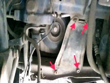
Using a 13 key, unscrew the nuts securing the amplifier and remove it
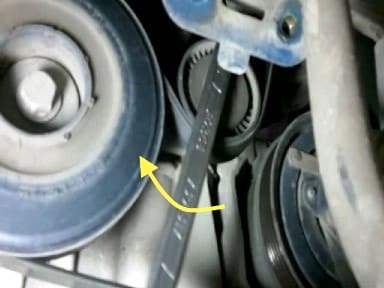
With a 16 spanner, turn the drive belt tensioner and remove the drive belt of the units
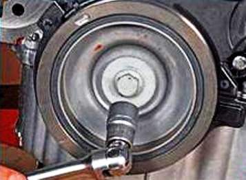
We unscrew the bolt securing the belt drive pulley of additional units.
To unscrew the bolt, block the crankshaft from turning.
In we switch to the highest gear in the manual transmission and the assistant presses the brake pedal.
Jacking the engine through a soft spacer.
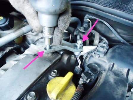
Unscrew the two bolts and remove the brace
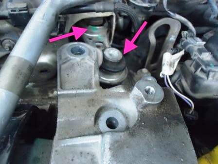
We unscrew the two bolts securing the right rear support of the power plant
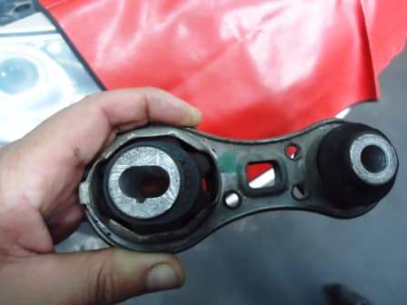
Manipulating with a jack or a lift, we remove the right rear support of the power unit
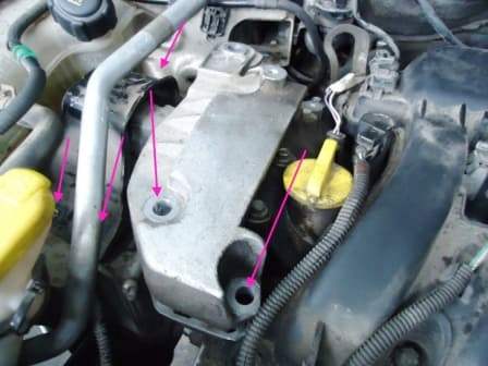
We unscrew the bolts of the right front support.
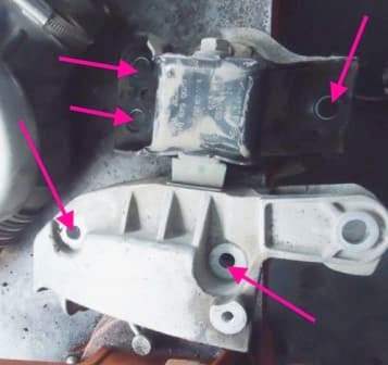
Raising and lowering the engine, remove the right front support, being careful not to damage the air conditioning tube
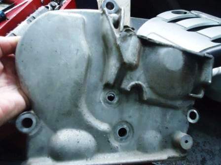
Unscrew and remove the upper timing cover through the technological holes
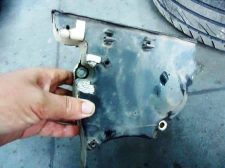
Unscrew and remove the lower timing cover
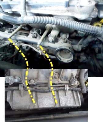
We unscrew the two nuts securing the heat sink cover from the cylinder head and remove it. (This is done for the top approach to insert the TDC retainer).
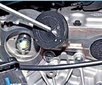
We pierce the technological plugs of the camshafts and remove them
In order not to disturb the valve timing, before removing the timing belt, it is necessary to set the crankshaft to the TDC position of the piston of the first cylinder.
To rotate the crankshaft, we screw in the bolt securing the alternator belt drive pulley by installing a bushing or a set of washers.
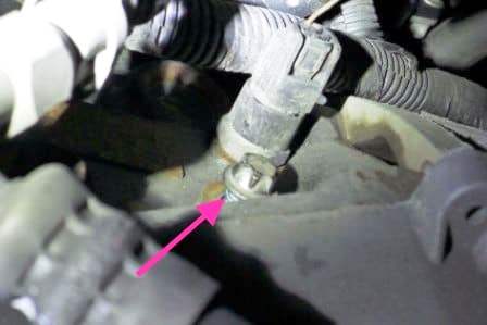
We unscrew the plug from the technological hole, designed to install the crankshaft retainer at TDC (Fig. 16).
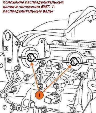
The grooves (1) offset from the axis of the camshafts must be below the axis and must be located almost horizontally with a slight offset.
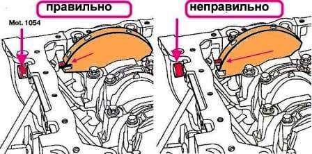
Insert the TDC lock so that it is between the hole on the balancer and the groove crankshaft lock.
Turn the crankshaft slightly in the direction of the working movement so that lock Mot. 1054 ended up in the crankshaft lock slot (Fig. 18).
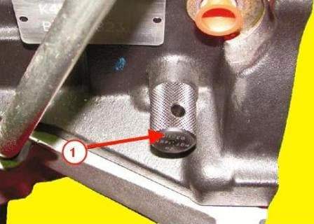
In Figure 19, the installed crankshaft retainer
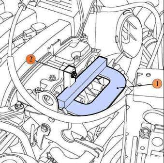
Insert tool Mot1496 into the grooves of the camshafts (Fig. 19).
Together with an assistant, unscrew the cover and the phase regulator bolt for this:
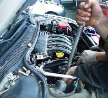
An assistant inserts a powerful slotted screwdriver between the slots of the phase regulator and thus fixes it from turning,
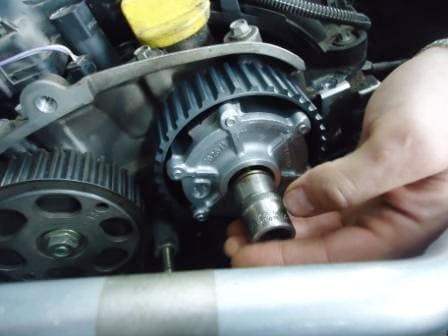
at the same time, unscrew the phase regulator cover and the phase regulator bolt.
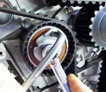
Loosen the tension roller and remove the roller
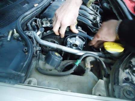
Remove the timing belt
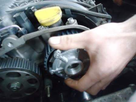
We take out the phase regulator.
Install the phase regulator in reverse order.
When installing, you need to take into account that you need to tighten the phase regulator last.
Before installing the phase regulator, degrease the bolt and the end of the intake camshaft.
The place where the phase regulator is attached must be clean and free of grease.
The tightening torques of the main components when replacing the phase regulator:
- - crankshaft pulley bolt 40 Nm and tighten 110˚;
- - nuts for fastening the toothed pulleys of the camshafts - 30 Nm and tighten by 86˚±6˚;
- - bypass roller bolts 50 Nm;
- - nut for fastening the axis of the tension roller - 28 Nm.


