The engine of the VAZ-2123 car is equipped with a microprocessor control system (MSUD), i.e. distributed fuel injection system with feedback, which combines inseparably interconnected power and ignition subsystems
Controls both subsystems in a complex electronic control unit (ECU), which receives information about the state of the engine from sensors that monitor various operating parameters of the system.
The location of the sensors is shown in fig. 1.
Spread injection is called because for each cylinder the fuel is injected by a separate nozzle.
The fuel injection system reduces the toxicity of exhaust gases while improving the driving performance of the car.
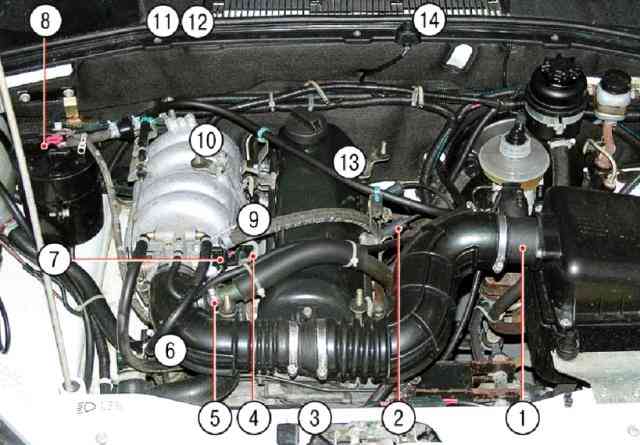
1 - mass air flow sensor; 2 - ignition module; 3 - crankshaft position sensor (not visible in the photo, installed near the crankshaft pulley); 4 - nozzles; 5 - idle speed regulator; 6 - coolant temperature sensor (not visible in the photo, installed in the pipe of the water jacket of the cylinder head); 7 - throttle position sensor; 8 - adsorber purge valve; 9 - knock sensor (not visible in the photo, located on the right side of the engine block); 10 - oxygen sensor (not visible in the photo, located on the exhaust pipe of the exhaust system): 11 - controller (not visible in the photo, located in the passenger compartment on the bulkhead of the bulkhead shield); 12 - relay and fuse block (not visible in the photo, installed together with the controller); 13 - vehicle speed sensor (not visible in the photo, installed on the transfer case); 14 - diagnostic connector (not visible in the photo, installed in the cabin next to the ignition switch)
The VAZ-2123-40 MSUD installed on the vehicle with the Bosch MP7.OH controller (2123–1411020–10) ensures Euro II toxicity standards.
This system uses a synchronous fuel supply method.
The injectors are switched on in pairs and in turn: first, the injectors of the 1st and 4th cylinders, and after 180 ° of the crankshaft turn, the injectors of the 2nd and 3rd cylinders, etc.
In this way, each nozzle is activated once per crankshaft revolution, i.e. twice in a full engine cycle.
In order to achieve Euro-IV toxicity standards, a phased injection method can be applied to parts of cars.
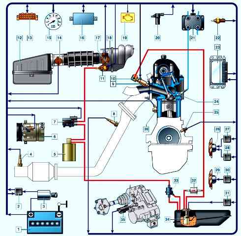
Scheme of the electronic engine control system: 1 - battery; 2 - main relay; 3 - ignition lock; 4 - diagnostic oxygen concentration sensor; 5 - adsorber; 6 - air conditioner compressor; 7 - adsorber purge valve; 8 - control oxygen concentration sensor; 9 - nozzle; 10 - fuel rail; 11 - idle speed regulator; 12 - air filter; 13 - diagnostic connector; 14 - mass air flow sensor; 15 - tachometer; 16 - immobilizer block; 17 - throttle position sensor; 18 - throttle assembly; 19 - control lamp for a malfunction of the engine management system; 20 - phase sensor; 21 - ignition coil; 22 - coolant temperature sensor; 23 - controller; 24 - spark plug; 25 - crankshaft position sensor; 26 - right fan of the cooling system; 27 - additional relay; 28 - relay of the right fan of the cooling system; 29 - left fan of the cooling system; 30 - relay of the left fan of the cooling system; 31 - fuel pump relay; 32 - fuel filter; 33 - gravity valve; 34 - fuel module; 35 - speed sensor; 36 - knock sensor
In this case, a phase sensor is additionally installed on the engine, which determines the moment of the end of the compression stroke in the 1st cylinder, and fuel is supplied by injectors to the cylinders in the sequence corresponding to the ignition order in the cylinders (1–3–4–2).
The ignition system does not use a traditional distributor and ignition coil.
Here, an ignition module is used, consisting of two ignition coils and high energy control electronics.
The ignition system has no moving parts and is therefore maintenance-free.
It also has no adjustments (including the ignition timing), since the controller controls the ignition.
The ignition system uses a spark distribution method called the "blank spark" method.
Engine cylinders are combined in pairs 1-4 and 2-3, and sparking occurs simultaneously in two cylinders: in the cylinder in which the compression stroke ends (working spark), and in the cylinder, in which the exhaust stroke occurs (idle spark).
Due to the constant direction of the current in the windings of the ignition coils, the sparking current for one spark plug always flows from the central electrode to the side electrode, and for the second - from the side to the central one.
The controller controls the ignition in the system.
The crankshaft position sensor supplies the controller with a reference signal, on the basis of which the controller calculates the sequence of operation of the coils in the ignition module.
The controller uses the following information to precisely control the ignition:
- – crankshaft speed;
- – engine load (mass air flow);
- – coolant temperature;
- - position of the crankshaft;
- – presence of detonation.
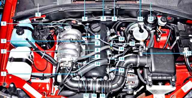
Location of elements of the electronic engine control system: 1* - coolant temperature sensor; 2* - control oxygen concentration sensor; 3* - knock sensor; 4 - solenoid valve for adsorber purge; 5* - controller, relay and fuse block of the engine management system; 6* - diagnostic oxygen concentration sensor; 7 - vehicle speed sensor; 8 - nozzles; 9* - immobilizer; 10* - ignition coil; 11* - diagnostic block; 12* - signaling device for malfunction of the control system; 13 - mass air flow sensor; 14 - spark plugs; 15* - crankshaft position sensor; 16* - phase sensor; 17 - throttle position sensor; 18 - idle speed regulator; (*) - Not visible in the photo.
In photo 3, the location of the elements of the CUD of a car from 2009 of release
Since 2015, the VAZ-2123 car has been equipped with an electronic engine control system with a controller ME17.9.71 2123-1411020-50 under EURO-5 toxicity standards.
This system is described in the article - Engine management system EURO-5 Niva Chevrolet
The electronic engine control system (ECM) consists of a controller, sensors for engine and vehicle operation parameters, as well as actuators.
The controller is a mini-computer for special purposes, it consists of random access memory (RAM), programmable read-only memory (PROM) and electrically reprogrammable memory (EPROM).
RAM is used by the microprocessor to temporarily store current information about the operation of the engine (measured parameters) and calculated data.
Also, fault codes are recorded in the RAM.
This memory is volatile, i.e. when the power is interrupted (disconnecting the battery or disconnecting the wiring harness block from the controller), its contents are erased.
EPROM stores the engine control program, which contains a sequence of operating commands (algorithms) and calibration data (settings).
PROM determines the most important parameters of engine operation: the nature of the change in torque and power, fuel consumption, ignition timing, composition of exhaust gases, etc. PROM is non-volatile, i.e. the contents of its memory do not change when the power is turned off.
ERPROM stores controller, engine and vehicle IDs.
Records operating parameters as well as engine and vehicle malfunctions. It is a non-volatile memory.


