The automatic transmission PCM is integrated with the engine control unit.
The vehicle's PCM outputs a control signal to the engine and transmission according to the signals from all sensors and/or switches
The automatic transmission control unit is responsible for the operation of the pump, control valve, solenoid valves, hydraulic accumulators, lockup clutches and brakes.
The main pressure in the hydraulic system of an automatic transmission is created by a pump, it is regulated by the control system depending on the load and vehicle speed and ensures the operation of the torque converter, lock-up clutches and brakes.
Shift valves control fluid flow to the torque converter and planetary gearbox.
The valve block has three solenoid valves that control gear shifting and torque converter lockup.
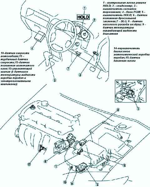
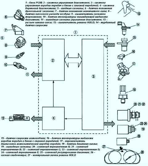
Fig.1 Mazda 3 electronic control system: 1 – HOLD mode control lamp; 2 – speedometer; 3 – the switch of signals of braking; 4 - block PCM; 5 – HOLD switch; 6 - throttle position sensor; 7 - DLC; 8 - mass air flow sensor; 9 - engine coolant temperature sensor; 10 - vehicle speed sensor; 11 – turbine speed sensor; 12 - crankshaft position sensor; 13 - control valve (with gearbox fluid temperature sensor and solenoid valves); 14 – the switch of ranges of an automatic transmission; 15 - oil pressure sensorFig. 2 Block diagram of the Mazda 3 control system: 1 – PCM unit; 2 - engine management system; 3 - control system of the gearbox in the block with the main gear; 4 – system of onboard diagnostics; 5 – input signals; 6 - throttle position sensor; 7 - crankshaft position sensor; 8 - mass air flow sensor; 9 – the switch of signals of braking; 10 - engine coolant temperature sensor; 11 – engine control output signals; 12 – communication channel connector; 13 – HOLD mode switch; 14 – turbine speed sensor; 15 - vehicle speed sensor; 16 - gearbox fluid temperature sensor in the block with the main gear; 17 – the switch of ranges of an automatic transmission; 18 - oil pressure sensor; 19 - output signals; 20 - switching solenoid A; 21 - switching solenoid B; 22 - switching solenoid C; 23 - switching solenoid D; 24 - switching solenoid E; 25 - pressure control solenoid; 26 - speedometer signal; 27 - HOLD indicator light

")
")
")
")
")
")