")
")
")
")
")
")
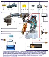
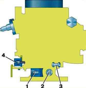
K-131 carburetor (Fig. 1) - vertical, balanced, with a falling flow, single-chamber, two-diffuser
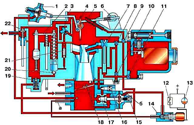
Main dosing system - with pneumatic braking of fuel and emulsification in the well, with a central supply of air emulsification.
In addition, the carburetor has an autonomous idle system and a semi-automatic starting and warm-up system.
Carburetor maintenance consists in periodically checking the reliability of fastening the carburetor and its individual elements, checking and adjusting the fuel level in the float chamber, adjusting the low engine speed in idle mode, checking the operation of the accelerator pump and economizer, cleaning, purging and flushing carburetor parts from resinous deposits, checking the throughput of jets.
Check the fuel level when the engine of the car is installed on a horizontal platform.
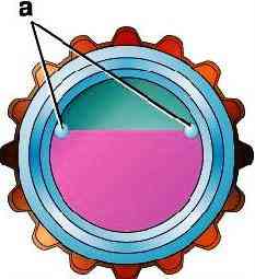
When pumping fuel using a manual drive of the pump, the fuel level in the carburetor float chamber should be set within the limits marked with marks (tides) "a" (Fig. 2) on the walls of the viewing window.
If the level deviates from the specified limits, adjust by removing the cover of the float chamber.
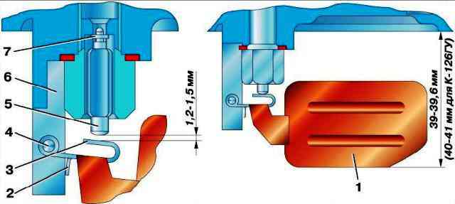
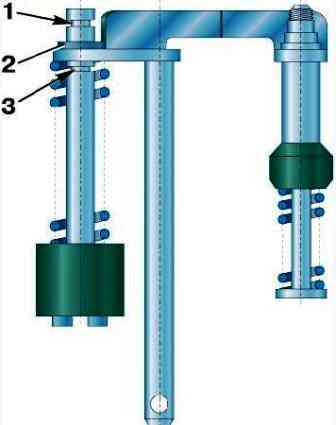
Adjust the level by bending tab 3 (Fig. 3).
At the same time, by bending the limiter 2, set the stroke of the needle 5 of the fuel supply valve to 1.2–1.5 mm.
After adjusting, check the fuel level again and re-adjust if necessary.
Given that during operation, due to the wear of the float mechanism, the fuel level gradually rises, set it when adjusting to the lower limit.
In this case, the fuel level will remain within acceptable limits for a longer time.
When adjusting the fuel level in the carburetor float chamber, do not bend the float tongue by pressing the float, but bend it with a screwdriver or pliers.
Adjust the low speed of the crankshaft in idle mode on a warm engine with a good ignition system.
Adjust in the following order:
- 1. Preliminarily set with screw 2 (Fig. 4) the idle speed of the crankshaft 550–600 min -1 .
- 2. Set screw 1 to the position that provides the highest engine speed at a given throttle position.
Screw 1, in addition, regulate the CO content in the exhaust gases.
- 3. Finally set screw 2 to a low idle speed (550–650 min -1).
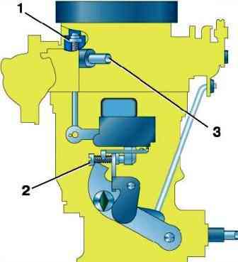
- 4. Adjust the valve actuator 1 (Fig. 5) for unbalancing the float chamber with screw 3.
The valve should be open when the throttle is fully released.
Check the operation of the accelerator pump in the event that when you sharply press the throttle pedal, dips are observed in the engine operation, and the engine slowly increases the speed.
To check, open the throttle sharply, while fuel should flow from the accelerator pump nozzle.
On a special stand, you can check the flow of the accelerator pump, which must be at least 8 cm 3 for 10 piston strokes.
During the operation of the carburetor, due to wear of the piston and walls of the well of the accelerator pump, its supply may be insufficient.
To increase the flow, move the restrictive washer 2 (Fig. 6) on the accelerator pump rod to the lower groove 3.
When operating the car in high-temperature conditions, reduce the flow of the accelerator pump by moving the restrictive washer to the upper groove 1 of the rod.
If the engine does not develop maximum power at wide open throttle, check that the economizer is fully engaged.
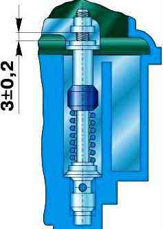
To do this, check the gap between the plate and the economizer drive rod nut at full throttle, which should be (3 ± 0.2) mm (Fig. 7).
If necessary, adjust this clearance with a nut, then secure the nut by crimping it over a small diameter.
The capacity of jets is determined on a special stand by pouring water through them under pressure (pressure) of a column of water 1000 ± 2 mm high and at a temperature of (20 ± 1) ° C.
Jet capacity, ml/min:
- - main fuel jet 350±4.5
- - idle fuel jet 55±1.5
- - main air jet 175±4
- - idle air jet 290±7
Be careful not to damage the threads in the holes when screwing in and out the jets.
Keep in mind that the main jet and the idle jet are similar in appearance, but have different threads.
Rinse carburetor parts with benzene or unleaded gasoline, then blow them out with compressed air.
Do not use metal wire to clean jets and calibrated holes, as this will lead to a violation of their size and throughput.
In case of failure of the electronic unit 13 (see Fig. 1) or microswitch 12 on the way, connect the fittings "a" and "b" of the carburetor to each other with one of the hoses, bypassing the solenoid valve.