Removing and installing intake manifold (K4J engine)
Disconnect the wires from the battery terminals, starting with the negative terminal.
Remove the air filter housing.
Remove the throttle body.

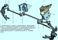
Fig. 1. Scheme of the intake tract (K4M engine): 1 - air intake pipe; 2 - intake silencers; 3 - air filter housing; 4-block throttle; 5 - intake manifold; 6 - lining of nozzle bodies; 7 - air intake
Scheme of the intake tract (K4M engine Fig. 1, F4R engine - Fig. 2).

Fig. 2. Scheme of the intake tract (engine F4R): 1 - air intake; 2 - intake silencers; 3 - air filter housing; 4 - turbocharger; 5 - air cooler; 6 - intake manifold inlet
Remove the throttle body

Squeeze the retainer of the fuel rail hose end

Disconnect the hose from the fuel rail

We press the retainer of the fuel injector wiring harness block

Disconnect the pads and remove pad A from the bracket

We press the retainer of the block of the wiring harness of the pressure sensor in the receiver
Disconnect the block from the sensor
Press the retainer of the air temperature sensor harness block in the receiver

Disconnect the block from the sensor

Disconnect the wiring harness connectors from the ignition coils

Remove the receiver mounting bolts

Remove the receiver

Pry off the O-rings with a screwdriver
Remove the O-rings. When installing, replace the O-rings.
Remove the fuel rail

Remove ten bolts securing the intake pipe

Remove the intake pipe

Remove the intake pipe gasket

Install the intake pipe and all parts in reverse order
Installation
All seals must be replaced. Installation is carried out in the reverse order of removal.

In the order shown in figure 5, tighten the intake manifold mounting bolts (fig. 5) to the required torque (9 Nm) (fig. 5).
Torque tighten:
- - throttle body mounting bolts (13 Nm);
- - air filter housing mounting bolts (9 Nm).
Connect the wires to the battery terminals, starting with the positive terminal.
Removing and installing the intake manifold (K4M, F4R engines)
Withdrawal
Disconnect the wires from the battery terminals, starting with the negative terminal.
Remove the top engine covers.
Remove the air duct.
Disconnect the wiring harness from the throttle body, the brake booster vacuum hose from the intake manifold.
Be careful not to damage the vacuum connection on the intake manifold. If the nozzle is broken, replace the manifold.
Disconnect the EVAP line from the throttle body.
Disconnect the wiring harness and move it aside.
Disconnect the fuel supply line from the fuel rail.
Disconnect the fuel vapor control system line from the intake manifold.

Removing the intake manifold of the K4M engine: 1 - throttle cable; 2 - block of the wiring harness to the ignition coils; 3 - block of the wiring harness to the air temperature sensor; 4 - block of the wiring harness to the incoming air pressure sensor; 5 - intake manifold
Remove the intake manifold mounting bolts (fig. 6).
Remove the throttle body.
Installation
All gaskets must be replaced.
Installation is performed in the reverse order of removal.

Torque tighten (9 Nm) in the order shown in figure 7 the intake manifold mounting bolts.
Tighten to torque (13 Nm) the motorized throttle valve mounting bolts evenly and alternately.
Connect the wires to the battery terminals, starting with the positive terminal.
Removing and installing exhaust manifold (K4J, K4M engines)
Withdrawal
Put the car on a two-post lift.
Disconnect the wires from the battery terminals, starting with the negative terminal.
Remove the air filter housing (K4J).
Remove the intake manifold (K4M).

Disconnect the wiring harness from the downstream oxygen sensor (fig. 8).

Unscrew the nuts securing the exhaust pipe flange and remove the exhaust manifold brace (Fig. 9).
Mark the position of the exhaust pipe suspension brackets on the body with a marker.

Remove the bolt securing the exhaust pipe suspension bracket to the body (Fig. 10).

Remove the bolt securing the main muffler suspension bracket to the body (Fig. 11).
Move the exhaust pipe back.
Remove the oxygen sensor using tool (Mot1495-01).

Remove the top exhaust manifold heat shield (fig. 12).

Unscrew the nine nuts of the mounting studs and remove the exhaust manifold (Fig. 13).

Remove the lower heat shield (fig. 14).
Installation
Subject to mandatory replacement: - collector gaskets;
- - exhaust pipe flange gaskets;
- - exhaust manifold stud nuts.
Installation is performed in the reverse order of removal.

In the order shown in figure 15, to the required torque (23 ± 3 Nm), tighten the nuts of the exhaust manifold mounting studs.
Tighten:
- - heat shield mounting bolt (10 Nm);
- - oxygen sensors (45 Nm);
- - bolts for fastening the exhaust pipe suspension brackets to the body (21 Nm);
- - strut mounting bolt on the exhaust manifold (8 Nm);
- - exhaust pipe flange mounting nuts (20 Nm).
Connect the wires to the battery terminals, starting with the positive terminal.
Removing and installing exhaust manifold (F4R engine)
Withdrawal
Disconnect the wires from the battery terminals, starting with the negative terminal. Remove the power unit and turbocharger.

Unscrew the nuts of the mounting studs and remove the exhaust manifold (Fig. 16).
Installation
Installation is performed in the reverse order of removal.

In the order shown in figure 17, to the required torque (20 Nm), tighten the exhaust manifold stud nuts.
Install the turbocharger and power unit.
When removing and installing the turbocharger, the repair procedure must be strictly followed to ensure the tightness of the system.
Failure to follow these instructions may result in reduced driver safety.
")
")
")
")
")
")