The location of the elements of the crankcase ventilation system (K4J engine) is shown in fig. 1
At low loads, oil vapors are sucked in small quantities through the calibrated orifice.
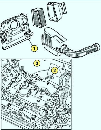
At medium to heavy loads, oil vapors are sucked in large quantities through the throttle body.
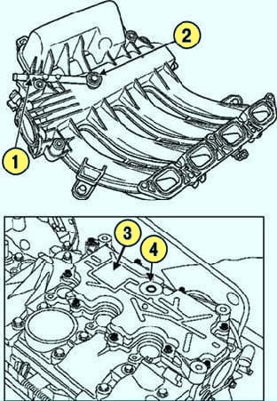
Location of elements of the crankcase ventilation system (K4M engine): 1 - crankcase ventilation pipeline; 2 - calibrated hole; 3 - oil separator of the crankcase ventilation system on the cylinder head cover; 4 - inlet of the crankcase ventilation system
To ensure proper operation of the emission control system, keep the crankcase ventilation system clean and in good condition.
Cleaning the ventilation system
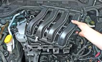
Removing the receiver
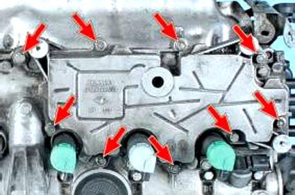
We unscrew the nine bolts securing the oil separator to the cylinder head cover
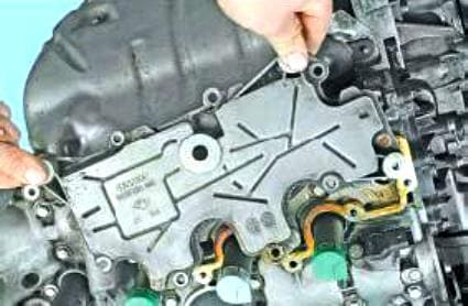
Remove the oil separator
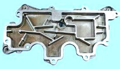
Cleaning the oil separator from deposits from crankcase gases
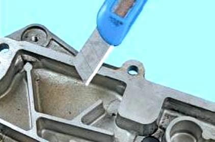
Remove the remnants of the old sealant from the mating surface of the oil separator
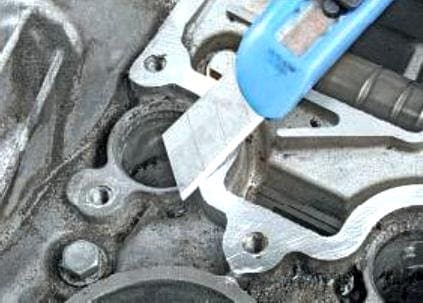
Cleaning the remnants of the old sealant from the cylinder head cover
We apply a special sealant to the mating surfaces of the cylinder head cover and oil separator
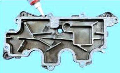
Install all parts in reverse order.
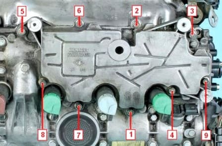
Tighten the oil separator mounting bolts to a torque of 13 Nm in the order shown in Figure 10.


