The turbo boost pressure regulator stem cannot be adjusted
Remove the turbocharger
The test cannot be performed with a turbocharger installed.
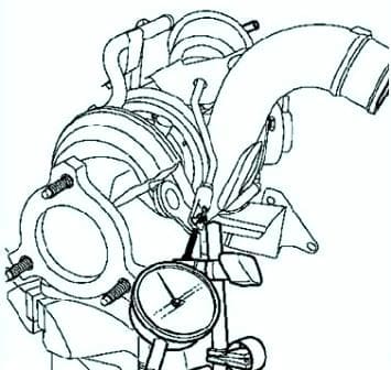
Use a magnetic stand with an indicator, the leg of which is installed on the end of the boost pressure regulator valve actuator rod (as far as possible coaxially with the rod) (Fig. 1).
Apply pressure gradually to the pressure regulator air actuator using a vacuum pump.
At a pressure of 331 Mbar, the stroke is 1 mm.
At a pressure of 544 Mbar, the stroke is 5 mm.
Boost pressure control solenoid valve
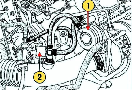
The pneumatic actuator of the boost pressure regulator is controlled by a solenoid valve at the commands of the injection computer (Fig. 2).
The boost pressure regulator is controlled by a solenoid valve in response to commands from the injection computer.
In the initial position, the boost pressure regulator valve is closed and the solenoid valve is open.
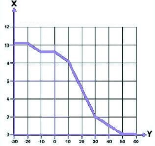
In the open position, the solenoid valve connects the turbocharger output (boost pressure) to the air actuator, so the boost pressure acts directly on the air actuator and the pressure regulator valve opens.
When the solenoid valve is controlled, the boost pressure signal (measured at the outlet of the turbocharger) is applied to the inlet of the turbocharger.
Consequently, boost pressure is removed from the pneumatic actuator and the pressure regulator valve closes.
After starting the engine, the supply voltage is supplied to the solenoid valve, which is open in the initial position.
For a certain period of time, the duration of which depends on the temperature of the coolant, the boost pressure is limited and the engine speed cannot exceed 2500 min–1.
This is necessary so that the oil can reach the turbocharger bearings.


