The transfer box is designed to change the torque in magnitude and distribute it between the front and rear drive axles
The car is equipped with a two-stage transfer case with an interaxle locking differential.
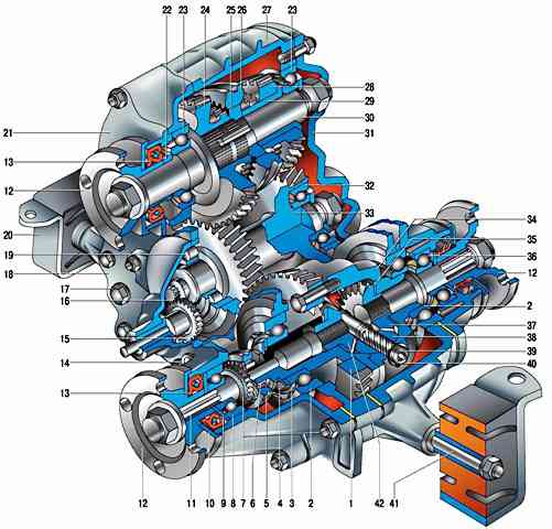
Fig. 1. transfer case: 1 - driven gear; 2 - differential bearings; 3 - spring washer; 4 - retaining ring; 5 - differential lock clutch; 6 - gear ring of the differential case; 7 - gear rim of the front axle drive shaft; 8 - front axle drive shaft bearing; 9 - oil deflector; 10 - mud deflector; 11 - front axle drive shaft; 12 - flange 13 - stuffing box; 14 - oil drain plug; 15 - driven gear of the speedometer drive; 16 - drive gear of the speedometer drive; 17 - hole plug for filling and oil level control; 18 - front cover of the transfer case; 19 - roller bearing of the intermediate shaft; 20 - transfer box suspension bracket; 21 - bearing cover of the drive shaft; 22 - bearing thrust ring; 23 - bearings of the drive shaft; 24 - overdrive gear; 25 - gear shift clutch hub; 26 - gear shift clutch; 27 - transfer case housing; 28 - downshift gear; 29 - low gear bushing; 30 - drive shaft; 31 - back cover; 32 - ball bearing of the intermediate shaft; 33 - intermediate shaft; 34 - differential case; 35 - thrust washer of the rear axle drive gear; 36 - bearing of the rear axle drive shaft; 37 - rear axle drive gear; 38 - satellite; 39 - axis of the satellites; 40 - retaining ring of the axis of the satellites; 41 - transfer case suspension axis; 42 - spring washer; 43 - front axle drive gear
They control the transfer case (upshift or downshift selection, engagement / disengagement of the differential lock) with one lever through a mechanical lever drive.
The transfer case is used to change the amount of torque and distribute it between the front and rear axles.
The box has two gears with ratios of 1.200 and 2.135.
The front and rear axles are constantly driven and connected by an interaxle differential that redistributes the torque between them depending on the resistance to the movement of the wheels.
To increase the cross-country ability of the car, the differential can be blocked, while the front and rear drive shafts become rigidly interconnected (their speeds are equal).
The transfer box is attached to the body floor on two rubber-metal brackets.
To adjust its position relative to the intermediate shaft flange, the holes in the brackets are made oval, and shims can be installed between them and the body.
To center the box, see Determining Causes of Vibration and Centering the Transfer Case.
The body parts of the transfer case are cast from aluminum alloy and are interconnected with studs and nuts.
A hatch is made in the upper part of the crankcase, closed with a stamped steel cover.
The front cover is centered on the crankcase by two dowel pins.
There are cardboard gaskets between the covers and the crankcase (when repairing, you can use a gasket sealant instead).
All shafts (including the speedometer drive roller), as well as the shafts of the gearshift and differential lock forks, are sealed with oil seals.
There are two holes in the front cover - a filler (it is also a control) and a drain.
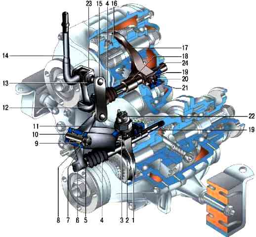
Fig. 2. Transfer case drive: 1 - fork of the differential lock clutch; 2 - differential lock clutch; 3 - fork locking bolt; 4 - protective cover of the rod; 5 - lever spring; 6 - differential lock fork rod; 7 - front axle drive housing cover; 8 - lock washer; 9 - bushing of the lever axis; 10 - axis of the lever; 11 - differential lock lever; 12 - a rod of a fork of a gear change; 13 - fork of the control lever; 14 - control lever; 15 - thrust of the differential lock lever; 16 - gear shift clutch; 17 - fork of the gear shift clutch; 18 - remote bushing; 19 - retainer ball; 20 - latch spring bushing; 21 - retainer spring; 22 - switch of a control lamp of blocking of differential; 23 - axis of the fork of the control lever; 24 - fork mounting bolt
The drive shaft is mounted on two ball bearings in the sockets of the front cover and crankcase.
The inner race of the front bearing is sandwiched between the shoulder of the shaft and the thrust shaft flange self-locking nut.
The rear bearing inner race is sandwiched between the shoulder of the shaft and the thrust washer and nut at the rear end of the shaft.
The nut is locked by pressing its edge into the grooves on the shaft.
The drive shaft is fixed against axial displacement by a set ring in the groove on the outer ring of the rear bearing and sandwiched between the crankcase and the rear cover.
There are two drive gears on the drive shaft.
The front (large) is the highest gear, it rotates freely on a heat-treated shaft journal. The rear (smaller) - low gear - rotates freely on a heat-treated bushing mounted on the shaft with an interference fit.
Gears have two crowns. The helical (large) rims are in constant engagement with the corresponding gears of the intermediate shaft, and the gear shift clutch is connected to the spur (small) rims when the gear is engaged.
The clutch moves along a hub rigidly fitted on the splines of the shaft between the drive gears.
In the middle position of the clutch, both gears are off ("neutral") and the torque from the engine is not transmitted to the wheels.
The intermediate shaft is a block of two helical gears that are in constant mesh with the gears of the input shaft.
The front gear is also in mesh with the driven gear mounted on the differential housing.
The intermediate shaft rotates in two bearings: the front - roller, rear - ball.
The shaft is fixed against axial displacement by a set ring in the groove of the outer ring of the rear bearing, which is sandwiched between the crankcase and the rear cover (same as for the drive shaft).
A steel speedometer drive gear is pressed into the front end of the shaft.
The driven gear of the speedometer drive is plastic, mounted on a roller rotating in the sleeve of the speedometer drive housing. The case is fixed on the front cover of the transfer case.
The front axle drive shaft rests with its front end on a ball bearing in the front axle drive housing, mounted on the front cover of the transfer case.
The bearing inner race is clamped between the shaft shoulder and the thrust washer by a self-locking shaft flange nut.
The bearing is fixed against axial displacement by a retaining ring, which is included in the groove of the front axle drive housing.
The rear splined end of the shaft is connected to the drive gear of the front differential axle.
A spur gear on the shaft is used to lock the differential. The design and installation of the rear axle drive shaft is similar, but there is no gear on it.
The differential housing is made detachable, both parts are connected by six bolts.
These same bolts secure the driven gear to the differential housing. The latter is mounted on two ball bearings.
The inner ring of the front bearing is kept from moving by a spacer spring washer resting on a retaining ring in the groove of the differential housing.
The groove on the outer race of the bearing includes a set ring sandwiched between the transfer box front cover and the front axle drive housing.
Thus, the differential housing is held against axial displacement by the front bearing; the rear bearing is not fixed.
On the front of the differential housing there are slots along which the lock-up clutch moves.
When the lock is engaged, the clutch connects to the gear on the front axle drive shaft, connecting it to the differential case.
The axle of the pinion gears is installed in the holes of the differential housing, held by two retaining rings. Under one of the rings there is a spring washer that prevents axial movement of the axis of the satellites.
The satellites (bevel gears) located on the axle are in constant engagement with the axle drive gears.
Back-up washers are installed between the differential housing and pinion gears.
Their thickness is selected so that the axial clearance of the axle drive gears does not exceed 0.10 mm, and the moment of resistance to rotation is 14.7 Nm.
The transfer case is operated manually, with a mechanical lever drive.
The driver shifts gears with the rear lever, and the differential lock is activated with the front lever. The design of the gearbox control drives is similar.
The lever swings in the longitudinal direction on the axis installed in the bracket lugs in front of the transfer case.
Plastic bushings are inserted into the lever hole to reduce friction. The lower end of the lever enters the groove of the rod and is fixed with a curly spring.
The other end of the rod is connected to the fork of the corresponding clutch (gear shift or differential lock) and is locked with a bolt.
The stem at the outlet of the box is sealed with a stuffing box and protected from dust by a rubber corrugated cover.
To fix the actuator in the selected position, a ball detent is used - a spring-loaded ball enters the grooves on the rods.
There are three of them on the gearshift rod - for "neutral", higherth and lower gears, on the differential lock rod - two (“on” and “off”).
A switch is screwed into the cover of the front axle drive, which closes the control lamp circuit when the differential lock is engaged.
Possible malfunctions of the transfer case VAZ-2123
Cause of malfunction - Remedy
Vibration of the transfer case and body floor (in the area of the front seats) in all driving modes
Failure of intermediate shaft flexible coupling - Replace flexible coupling
Vibration of the transfer case and body floor (in the area of the front seats) when starting the car from a stop and accelerating to 80 km/h
Loose or damaged transfer box mountings and rear powertrain mounting - Tighten nuts and mounting bolt, replace damaged mountings
Tight rotation or binding in one of the planes of the hinges of the front or rear driveshafts - Repair the universal joints or replace the joints in the assembly
Incomplete release of the parking brake - Adjust the parking brake actuator
Tight rotation of the intermediate shaft constant velocity joint - Check the condition of the boot and the joint. If the hinge parts are worn or damaged, replace the hinge assembly
Vibration of the transfer case and body floor (in the area of the front seats) in the steady state of motion (at a speed of 80-90 km/h)
Increased cardan shaft imbalance - Repair or replace cardan shafts
Increased unbalance of the center differential of the transfer case - Replace the center differential
Front or rear driveshaft universal joints sticking - Repair the joints or replace the driveshaft assemblies
Intermediate shaft CV joint sticking - Check boot and joint condition. If parts are damaged, the hinge must be replaced
Loose engine mount nuts and bolts or damaged engine mounts - Tighten mount nuts and bolts or replace mounts
Bent bolts and jackshaft flexible coupling flange - Replace bolts or jackshaft
Difficulty shifting or differential lock
Couplings sticking on the splines of the hub, differential housing, front axle drive shafts - Clean burrs, nicks or scuffs, replace damaged parts
Nicks on the teeth of the small ring gears of high or low gears, as well as on the teeth of the couplings and on the splines of the front axle drive shaft - Clean out the nicks and burrs, replace damaged parts
Bent yoke or stem - Straighten deformed parts
Drive lever sticking to the axles - Remove the drive lever, clean the axles and bushings. Replace damaged parts. Lubricate the parts with Lithol
Contamination or corrosion in the control joints - Clean parts, replace damaged ones
Spontaneous disengagement of gears or differential lock
Worn gear teeth and clutches - Replace worn parts
Reduced detent springs or worn detent parts - Replace springs or worn parts
Incomplete engagement of gears and lack of differential lock due to deformation of drive parts or due to nicks on gears, couplings and splines - Straighten or replace deformed parts, clean nicks and burrs, replace damaged parts
Oil leak
Damaged gaskets - Replace gaskets
Loosen the nuts and studs securing the covers to the crankcase - Tighten the nuts and studs
Worn or damaged shaft seals - Replace seals
O-rings worn on transfer case drive rods - Replace O-rings
Bells, porosity and damaged surfaces of body parts - Replace body parts
Methodology for determining the causes of vibration of the transfer case and body floor (in the area of the front seats)
First of all, note at what speed the transfer case vibration occurs, then proceed to determine the causes of vibration.
In case of vibration after repair or replacement of transmission units:
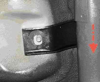
Raise the car on a lift to a height convenient for work, loosen the fastening nuts the cross member of the gearbox support to the car body and move the unit to the left until it stops (Fig. 3).
Tighten the nuts in this position. The arrow in the figure indicates the direction of the vehicle.
If the defect persists, center the transfer case:
- set the gear shift knob of the transfer case to the neutral position.
Start the engine, shift into second gear with the shift lever.
The car must not move. Raise the car on a lift to a height convenient for work;
- - loosen the six nuts securing the transfer case to the body;
- - turning the transfer case on studs, achieve such a position of the transfer case relative to the body, in which the vibration of the intermediate cardan shaft is minimal;
- - while holding this mode, tighten the nuts securing the transfer case to the body
- - lower the car, stop the engine.
Attention. The presence of people in the car during its lifting and repair is prohibited.
Use extreme caution when working under a vehicle. To avoid injury, keep hands and tools away from the rotating parts of the transmission.
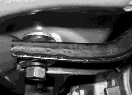
If the defect persists, install additional washers (fig. 4) with a thickness of 2.5 mm between the transfer box rear support cross member and the car body (one washer for each stud).
If the defect persists, reinstall the rear driveshaft, for which:
- - unscrew the bolts securing the cardan shaft to the flanges of the transfer case and the rear axle gearbox;
- - turn the shaft relative to the flanges of the transfer case and the rear axle gearbox by 180°;
- - fix the shaft in this position.
If the defect persists, reinstall the front cardan in the sequence indicated above.
If the defect persists, replace the rear driveshaft.
If the defect persists, replace the front driveshaft.
If the defect persists, replace the intermediate cardan shaft.


