This article describes the diagnostic procedure used for the electronic control unit (ECU) EMS 31.32 electronic engine management system (ECM) K7M and K4M
Required diagnostic equipment and instruments:
- - diagnostic device DST-12 (firmware RF90);
- - multimeter;
- - contact board Ele. 1497;
- - universal contact board Ele. 1681.
Contact board Ele. 1497 or universal contact board Ele. 1681 must be used if the data obtained from the diagnostic tool requires checking the electrical circuits.
Checks using the contact board Ele. 1497 or Ele. 1681 should only be performed with the battery disconnected.
Terminal boards are for use with a multimeter only. It is forbidden to connect a 12 V power supply to the tested points.
General instructions for diagnostics
To diagnose the ECM, you must connect the diagnostic tool, turn on the "ignition" and perform the necessary operations (checking for malfunctions, checking for compliance with the data transmitted by the controller).
Checking for Trouble Codes
Faults are defined as "current" (active at the moment) or as "stored" (non-permanent, i.e. appearing under certain conditions and then disappearing or continuing to occur, but not detected under current conditions).
The fault status ("current fault" or "stored fault") is displayed on the scan tool and must be taken into account without affecting the ECM.
For a "current" fault, carry out the diagnosis according to the procedure given in the "Interpretation of faults" section.
For a "saved" malfunction, carry out diagnostics in accordance with the procedure given in the article - Interpretation of states, commands, parameters when diagnosing the Lada Largus ECM
If the fault is confirmed after performing the steps in the "Instructions" subsection, the fault is considered current.
Perform diagnostics in accordance with the procedure given in the article - Interpretation of states, commands, parameters when diagnosing the Lada Largus ECM
If the fault is not confirmed, check:
- - electrical circuits related to the faulty ECM;
- - connectors of these circuits (for the absence of traces of oxidation, deformation of contacts, etc.);
- - resistance of the faulty device;
- - the state of the wires (whether there is melted or broken insulation, traces of kinks, etc.).
Checking the compliance of data transmitted by the ECM
The purpose of the conformity check is to check the data displayed by the diagnostic tool (states and system parameters) that are out of tolerance and do not lead to the occurrence of fault codes.
Therefore, this step allows you to:
- - perform diagnostics for such faults that do not lead to the appearance of a fault code, but may correspond to the owner's complaint;
- - check the system performance and make sure that the malfunction does not reappear after repair.
This section presents diagnostics of states and parameters, as well as the conditions for its implementation.
If the condition is not correct or if the parameter is out of tolerance, refer to the relevant diagnostic items.
Owner Complaints - Troubleshooting Algorithm (FLS)
If the diagnostic tool check shows no faults, but the owner's complaint persists, use the appropriate ALP to correct the fault.
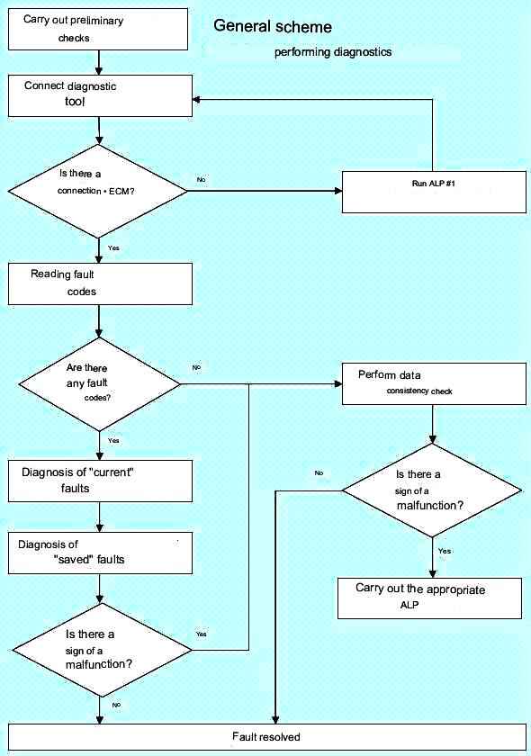
The general scheme for performing diagnostics is shown in Figure 1
Preliminary checks
When carrying out diagnostics, repairs or searching for the cause of a malfunction, it is always necessary to carefully inspect the engine compartment.
All vacuum hoses should be checked for kinks, cuts, or disconnections.
All electrical wiring located in the engine compartment must be checked for reliability of connections, the absence of burnt, frayed or deformed wires, the absence of wire contact with sharp edges or the exhaust manifold.
Check the ground wire contacts for contamination and a secure ground connection.
Check the wiring harnesses for damage. Check the integrity of the wire insulation.
Check the contacts of the connectors and blocks of the wiring harnesses for the absence of deformation and oxidation.
Checking wiring harnesses and system components
Finding faults that are intermittent should begin by checking problematic electrical circuits.
When checking electrical circuits, pay attention to the following:
- - the terminals are securely crimped on the wire, but the wires are not pinched;
- - the terminals are securely fixed in the block;
- - terminals are not deformed;
- - there is no dirt, moisture, corrosion on the terminals;
- - pad body does not contain any signs of damage (cracks, deformations, melting);
- - terminals provide a reliable connection, the terminals are not recessed in the block;
- - there are no insulation damages in the wires;
- - there are no breaks in the wires inside the insulation.
When intermittent faults occur, always check the continuity of the engine control system ground circuits.
It is necessary to make sure that the ground terminals are securely fastened to the car body, the power and ground wire terminals are securely fastened to the battery.
With the ignition on, and then with the car running, it is necessary to move the wires, starting from the connectors, along the entire route of the harness, controlling the parameters of the engine control system using a diagnostic tool.
When checking the resistance of a circuit, first check the integrity of the entire circuit, then in individual sections. The loss of electrical circuit integrity can be caused by the following reasons:
- - disconnection of the harness block;
- - weak connection of the harness block;
- - pollution, oxidation, corrosion of contacts;
- - contact deformation;
- - wire damage.
Determine if there is a short circuit in the circuit to ground or to the on-board network.
If a fault is found in the wiring harness, repair it or replace the wiring harness.
Safety measures
When working on a car, the following requirements must be observed:
Before dismantling the controller, disconnect the ground wire from the battery.
It is not allowed to start the engine without a reliable connection of the battery.
It is not allowed to disconnect the battery from the on-board network while the engine is running.
When charging, the battery must be disconnected from the on-board network.
It is necessary to control the reliability of the contacts of the wiring harnesses and keep the battery terminals clean.
The design of the wiring harness blocks provides for their connection with the mating part only in a certain orientation.
In the correct orientation, the connection of the harness socket to the mating part is effortless. Connecting with the wrong orientation of the pad can lead to failure of the pad, module or other element of the system.
It is not allowed to connect or disconnect blocks of ECM elements with the ignition on.
Before carrying out electric welding, it is necessary to disconnect the wires from the battery and the block from the controller.
To prevent contact corrosion, when washing the engine with a jet of water under pressure, do not direct the sprayer at the system elements.
Voltage measurements should be performed with a digital voltmeter with a nominal internal resistance of more than 10 MΩ.
To prevent electrostatic discharge damage to electronic components, do not disassemble the metal case of the controller and touch the connector plugs.
All work with the elements of the fuel system should be carried out with protective gloves.
When disconnecting the fuel lines, take measures to prevent spillage of fuel. Close fuel line openings using standard plugs
System operation
Features of the multipoint fuel injection system:
The 90-channel "EMS 31.32" ECU controls the fuel injection and ignition systems.
There is no camshaft position sensor in the system.
Therefore, synchronization of the system operation with the engine workflow is carried out programmatically according to the signal from the crankshaft position sensor. Fuel injection is carried out in series-parallel in accordance with the order of operation of the cylinders.
The idle speed is adjusted depending on:
- - state of the air conditioning system (air conditioner is working or not);
- - operation of the power steering system;
- - load on the onboard network.
The degree of cyclic opening (CDO) of the canister purge solenoid valve depends on the crankshaft speed and engine operating conditions.
Using two oxygen sensors installed before and after the catalytic converter.
Automatic configuration for air conditioning operation through the exchange of signals between the computer. Changing the configuration is not possible (including using the diagnostic tool).
Electronic countermeasure system engine start lock
Cars are equipped with an electronic anti-theft immobilizer. The ECM code must be entered into the ECM to operate.
Replacing the ECM
ECUs are shipped without an immobilizer code entered.
When replacing the ECU in a new unit, you must enter this code, then make sure that the electronic anti-theft engine immobilizer system is working.
To enter the code, you must turn on the ignition for a few seconds, and then turn it off.
The ECM retains the immobilizer code for its lifetime.
This system does not have an unlock code.
It is forbidden to carry out checks with ECUs taken from a warehouse or from another vehicle and subject to return. Codes entered into these ECUs cannot be deleted.
Check ECM status (code entered or not entered)
Check the status of the computer using a diagnostic tool:
- - connect the diagnostic tool to the diagnostic connector;
- - turn on the ignition;
- - select on the diagnostic tool: mode "Parameters" - "General view".
If status ET341 Immobilizer code entered is NO, this indicates that no code has been entered in the ECM.
If status ET003 Immobilizer system is ACTIVE, the engine cannot be started.
Control of the refrigeration circuit of the automatic climate control system (ACCS)
The following units provide the operation of the refrigeration circuit of the SAUKU:
- - SAUKU control unit;
- - air conditioner compressor;
- - ECM.
The system operates in automatic mode, i.e. the amount of cold air is dosed according to the set temperature.
How the system works
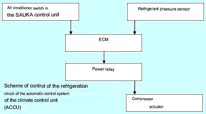
The block diagram of the system is shown in the figure
The air conditioner is turned on by pressing the "AC" air conditioner switch located on the instrument panel in the passenger compartment.
At the same time, the request to turn on the air conditioner is sent via a wired circuit to the ECM, which allows or prohibits turning on the air conditioner compressor, depending on the engine operating mode and the state of the automatic control system.
The ECM prevents the A/C compressor from turning on under the following conditions:
- - engine speed is below a certain value;
- - engine load above a certain value (for example, when the accelerator pedal is pressed sharply, on a steep slope or when the car is heavily loaded);
- - refrigerant pressure in the air conditioning system is above a certain value.
If there are no inhibit conditions, the ECM activates a power relay that supplies voltage to the A/C compressor actuator.
Correction of engine idle speed
Communication between the power steering pressure sensor (PSS) and the ECM (if the vehicle is equipped with power steering)
ECU receives signal from power steering pressure sensor (monitored by scan tool Options Mode - General View - Status ET297 - Power Steering Pressure Sensor - YES when steering wheel is turned) .
The parameters of the signal depend on the pressure of the working fluid in the hydraulic circuit of the power steering and on the viscosity of the working fluid. The higher the pressure, the more energy the power steering pump consumes.
At maximum load conditions, the idle speed can be further increased by about 100 rpm.
Correction of idle speed depending on the voltage of the battery and the load on the on-board network
If the battery is weakly charged, then when you turn on the electrical consumers
The voltage drop across it is compensated by the idle speed correction. To this end, the idle speed of the engine crankshaft increases, as a result of which the generator rotor speed increases and, accordingly, the battery charging current.
The lower the battery voltage, the greater the correction of the idle speed.
Thus, idle speed correction ist is a variable.
The correction starts when the battery voltage drops below 12.8 V. The rated idle speed can be increased by no more than 150 rpm as a result of the correction.
Adaptive engine idle correction
Under normal operating conditions of an engine warmed up to operating temperature, the value of the degree of opening of the idle speed regulator (IAC) changes from the upper to the lower value to ensure the nominal idle speed.
Due to the variety of engine operating conditions (break-in, mechanical wear, etc.), the IAC opening degree at idle may be close to the upper or lower limit.
Adaptive idling IAC opening adjustment compensates for operational changes in engine air demand to set the IAC opening to the average nominal value.
This correction is made if the coolant temperature is above 80 °C, at least 20 seconds have passed since the engine was started, and if the system is in the nominal idle speed control mode.
The values of the degree of IAC opening at idle and its adaptive correction
- PR145 "Engine speed" 752 rpm
- PR432 "Current IAC Opening Degree" 8% < X < 20%
- PR431 "Adaptive IAC opening degree" %
After each engine stop for 8 seconds, the ECU returns the IAC stepper motor valve to its original position to the lower stop.
Interpreting these parameters
In the event of excess air (due to air leaks, misadjustment of the throttle position, etc.), the engine idle speed increases and the IAC opening degree value decreases to maintain the nominal idle speed.
The IAC opening degree adaptive correction value is reduced to return the IAC opening degree to the average value.
When there is a lack of air (pollution, etc.), the reverse strategy is applied. The value of the degree of opening of the IAC increases.
The IAC opening degree adaptive correction value is increased to return the IAC opening degree to the average value.
After deleting information from the ECU memory, it is necessary to restore the adaptive engine idle correction function, for which follow the following procedure:
- - start and then stop the motor to correct the position of the IAC stepper motor;
- - start the engine again and leave it to idle until the nominal idle speed is set.
Regulating the composition of the working mixture
Heated oxygen sensors
ECU activates heated oxygen sensors:
- - for the upper sensor immediately after starting the engine,
- - for the lower sensor after a certain time of engine operation (excluding idle time) according to the program, depending on the temperature of the coolant.
Oxygen sensors are heated continuously until the engine stops.
Upper oxygen sensor signal voltage
The scan tool displays parameter PR098 Upstream oxygen sensor signal voltage.
The displayed value is the voltage (in millivolts) of the output signal given to the computer by the oxygen sensor located before the catalytic converter.
The ECM uses the signal from the upstream oxygen sensor to control the composition of the working mixture with feedback on the oxygen content in the exhaust gases.
The signal voltage of the upper oxygen sensor should change quickly in the range:
- - 20 mV + 50 mV lean;
- - 840 mV ± 70 mV for a rich working mixture.
The smaller the difference between the minimum and maximum values, the less accurate the information from the sensor (usually this difference is 500 mV).
Lower sensor signal voltage
The scan tool displays parameter PR099 Downstream oxygen sensor signal voltage.
The value displayed is the voltage (in millivolts) of the output signal given to the computer by the oxygen sensor located after the catalytic converter.
The functions of this sensor include diagnostics of the catalytic converter and the implementation of a second, more accurate, control of the richness of the mixture (slow control system).
This function is activated only after a certain time of operation of the engine warmed up to operating temperature, and is not implemented at idle.
At a steady speed, the signal voltage of the lower oxygen sensor should change in the range of 600 mV ± 100 mV.
When braking, the signal voltage must be below 200 mV.
Value The voltage displayed by the scan tool at idle is not used to diagnose the ECM.
Correction of the composition of the working mixture
The scan tool value for PR438 Air Ratio Correction Value is the average value of fuel injection time correction applied by the computer based on exhaust oxygen content information provided by the oxygen sensor upstream of the catalytic converter.
Correction value for nominal value 128 and for end positions 0 and 255:
- - value below 128 - lean request;
- - value above 128 - enrichment request.
Start of adjusting the composition of the working mixture
Entry into the mode of regulation of the composition of the working mixture occurs if the temperature of the coolant is more than 22 ° C and 28 seconds have passed since the engine was started.
Outside the mixture control phase, the correction value is 128.
Phase "breaking the mixture control circuit"
When adjusting the composition of the working mixture, the ECU does not take into account the voltage value of the oxygen sensor signal in the following cases:
- - in full load mode - correction value is higher than 128;
- - with a sharp acceleration - the correction value is higher than 128;
- - when braking with the signal "idle" (fuel injection stops) - the correction value is 128;
- - in case of a malfunction of the upper oxygen sensor - the correction value is 128.
Standby mode in case of oxygen sensor failure
If the voltage of the signal from the upstream oxygen sensor in the mixture control mode does not correspond to the set values \u200b\u200b(changes very little or no change at all) and this fault is recognized as "ongoing" for 10 seconds, the ECM will go into standby mode and information about this malfunction is entered into the memory of the computer.
If a "current" oxygen sensor malfunction is detected, the ECM will enter the mixture control open circuit mode.
In this case, the value of parameter PR438 Mixture correction value is 128.
Adaptive mixture correction
In exhaust gas oxygen feedback control (refer to "Ratio Control"), the mixture trim function changes the fuel injection duration to keep the excess air ratio as close to 1 as possible.
At the same time, the average correction value is close to 128, with the limit values of 0 and 255.
Operational changes to the parameters of the ECM and engine components can shift the correction values to 0 or 255 to provide an excess air ratio close to 1.
Adaptive mixture adjustment allows you to adjust the injection algorithm to obtain a value of 128 for parameter PR438 "Run mixture adjustment value" and use this value as the main value, both when the mixture is rich and when the mixture is lean.
There are two modes of adaptive adjustment of the mixture control:
- - adaptive correction, carried out mainly at medium and heavy engine load - "adaptive correction of the composition of the working mixture in load modes";
- - adaptive correction, carried out mainly at idle and low speed
engine load - "adaptive correction of the composition of the working mixture at idle".
Adaptive corrections take an average value of 128 after ECU initialization (erasing information from the ECU memory). During the operation of the car, adaptive corrections change and can take on the following values:
- - PR139 "Adaptive mixture adjustment under load conditions" 64 < X < 192
- - PR140 "Adaptive idle mixture adjustment" 64 < X < 192
Adaptive correction is performed only with the engine warmed up to operating temperature in the mode of controlling the composition of the working mixture by the signal of the oxygen sensor, and only at a given pressure range in the intake manifold.
In order for the adaptive correction to begin to compensate for deviations from the norm in the composition of the working mixture due to operational changes in the parameters of the ECM and the engine, it is necessary that the engine has been running for some time in the mode of regulation of the composition of the working mixture at various values of vacuum in the intake manifold.
After initialization of the ECU (adaptive mixture adjustments back to 128), a special road test must be carried out.
Road test
Conditions:
- - engine warm (coolant temperature > 80 °C);
- - engine crankshaft speed must not exceed 4000 rpm
It is recommended to start this road test at a low engine speed, in 3rd or 4th gear and with very smooth continuous acceleration to stabilize the required pressure for 10 seconds in each range (see table below) .
On the diagnostic tool, select the mode "Parameters" - "General view" - parameter "PR421 - Intake manifold pressure".
Test pressure ranges for the K7M engine are shown in the table.
After this test, the adaptive correction function starts to work.
The "Adaptive Idle Throttle" value changes more significantly at idle and light loads, and the "Adaptive Idle Throttle" value at medium and high loads.
Both types of correction are carried out over the entire range of pressure changes in the intake manifold.
Continue the test, moving under normal conditions at a constant and variable speed for a distance of 5 - 10 km.
After testing, check the adaptive correction values under load conditions.
Initially set to 128, they should change. Otherwise, carry out a road test again and check the adaptive correction values.
Features of the on-board diagnostics system
This vehicle is equipped with an on-board diagnostic system (OBD) that illuminates a warning light in the instrument cluster (on-board diagnostics warning light) when it detects that the exhaust gas toxicity level has been exceeded.
This warning light alerts the driver when the vehicle needs to be repaired.
The on-board diagnostics system includes the following types of diagnostics:
- - ECM elements diagnostics;
- - mixture misfire diagnostics;
- - functional diagnostics of the upper oxygen sensor;
- - catalytic converter diagnostics.
On an ongoing basis, diagnostics of ECM elements and diagnostics of mixture misfires are carried out.
Upstream Oxygen Sensor Functional Diagnosis and Catalytic Converter Diagnosis are performed once per trip if the appropriate diagnostic conditions are met:
- - air and coolant temperature conditions,
- - movement speed in a certain range;
- - engine operating conditions (intake manifold pressure and engine speed in a certain range of values, operation stability);
- - The specified initial time delay has elapsed.
In addition, the on-board diagnostics system is a means of detecting faults in electrical circuits. In this case, it is carried out:
- - storing faults detected by the on-board diagnostics system;
- - turn on the on-board diagnostics warning light (solid or flashing light, depending on the type of malfunction).
It must be borne in mind that some defects may only appear in motion after programming the correction parameters.
At the end of each diagnostic test, do not turn off the ignition until the result is read on the scan tool. Switching off the ignition leads to incorrect interpretation of the results.
Any electrical malfunction that exceeds the toxicity threshold will cause the on-board diagnostics warning light to turn on.
|
Range #1, mbar |
Range #2, mbar |
Range #3, mbar |
Range #4, mbar |
Range #5, mbar |
|---|---|---|---|---|
|
258 - 410 |
410 - 528 |
528 - 646 |
646 - 764 |
764 - 873 |
|
Average 334 |
Average 469 |
Average 587 |
Average 705 |
Average 818 |
On-board diagnostic warning light conditions
The OBD warning light comes on if the OBD has detected the same fault for three consecutive trips or if an electrical fault has been detected.
The flashing of the on-board diagnostics warning light occurs when a mixture misfire that is damaging to the catalytic converter is detected.
The on-board diagnostics warning light turns off if an on-board diagnostics malfunction does not occur for three consecutive trips (but the malfunction information remains in the ECM memory).
The fault is cleared from the ECM memory if the fault does not appear within 40 consecutive tests or with a scan tool.
Conditions for diagnostics by the on-board diagnostic system
The on-board diagnostic system starts functioning after the ignition is switched on and the following conditions are met:
- - the intake air temperature determined by the sensor is in the range from -6 °C to 119 °C;
- - the coolant temperature detected by the sensor is in the range from -6 °C to 119 °C;
- - the atmospheric pressure detected by the sensor with the engine off is above 775 mbar (altitude above sea level is below 2500 m).
For the correct operation of the on-board diagnostic system, there must be no malfunctions in the electrical circuits of the ECM, even if the SBD warning light does not light up.
Oxygen sensor and catalytic converter diagnostics cannot be done at the same time.
When diagnosing the catalytic converter and the oxygen sensor, the adsorber purge is stopped, and the adaptive parameters for correcting the composition of the working mixture are fixed at their last values.
Test order:
- - troubleshoot electrical circuits;
- - using the diagnostic tool, erase information about malfunctions from the computer memory;
- - if necessary, program all ECM settings.
Initializing the OBD system using command modes allows you to:
- - delete fault ECU from memory;
- - delete the programmed values of the ECM from the memory (if the programmed values of the idle speed controller, the marker section of the flywheel ring gear or the engine crankshaft position and speed sensor, etc., could be distorted during the repair work).
To do this, on the diagnostic tool, select the mode "Additional tests" - "Reset computer".
Programming required for OBD troubleshooting
Programming engine crankshaft torque (after programming, status ET061 Cylinder 1 recognition Adaptation of uneven rotation = Yes, with engine running).
Perform programming as follows:
- - perform engine braking with fuel injection cut off (i.e. without pressing the brake, accelerator and clutch pedals) in 2nd, 3rd, 4th or 5th gear from 3500 - 3000 rpm for at least 2 seconds;
- - perform engine braking with fuel injection cut off (i.e. without pressing the brake, accelerator and clutch pedals) in 2nd, 3rd, 4th or 5th gear from 2400 - 2000 rpm for at least 3 seconds.
Programming the parameters of the adaptive correction of the composition of the working mixture:
- to perform this programming, it is necessary to carry out a road test, observing the required pressure ranges in the intake manifold (see paragraph "Adaptive mixture correction").
After these programmings have been carried out, status ET422 "Misfire diagnostic results taken into account" should be "Yes".
Misfire Detection Diagnostics
Diagnosis detects:
- - dirty spark plugs;
- - malfunctions in the fuel supply system (pressure regulator, fuel pump, fuel injectors, etc.);
- - violation of electrical connections in the ignition and fuel supply systems (unreliable connection of high-voltage wires to spark plugs, wiring harness blocks to injectors, etc.).
Diagnosis is carried out by measuring the instantaneous engine speed. sharp falle torque indicates the absence of combustion of the fuel mixture in a particular cylinder.
This diagnostic is performed continuously while the vehicle is in motion. Identification of a malfunction in the process of conducting this diagnostic leads to a ban on other types of diagnostics by the system.
Misfire Detection Diagnostics detects two types of faults:
- - mixture misfires leading to the destruction of the catalytic converter (cause the on-board diagnostics warning light to flash immediately);
- - mixture misfires that lead to exceeding the permissible toxicity threshold (cause the on-board diagnostics warning light to illuminate if misfires are detected during three consecutive trips).
Troubleshooting Conditions
Using a scan tool, verify that the engine torque and adaptive mixture settings are programmed:
- -Status ET061 "Cylinder 1 recognition Adaptation of irregular rotation" is set to "Yes";
- Status ET422 "Misfire diagnostic results taken into account" is set to "Yes".
A misfire diagnostic test is performed with the engine idling for 11 minutes after the engine coolant temperature exceeds 75 °C in three engine speed ranges from idling to 4500 rpm.
If the diagnostic tool detects misfires after the test, refer to the interpretation of faults DF123 Misfire mixture resulting in an increase in toxic substances in the exhaust gases and DF124 Misfire mixture resulting in failure of the catalytic converter
Test execution confirmation:
- -Status ET061 "Cylinder 1 recognition Adaptation of irregular rotation" is set to "Yes";
- - state ET422 "Misfire diagnostic results taken into account" has the characteristic "Yes";
- - no faults detected and the on-board diagnostics warning light is off.
Catalytic converter diagnostics
A catalytic converter diagnostic is performed to detect a malfunction that is causing the exhaust emissions to exceed the threshold allowed by the on-board diagnostic system.
An indicator of the condition of a catalytic converter is its oxygen capacity. As a catalytic converter ages, its oxygen capacity decreases as does its ability to neutralize exhaust gases.
Conditions for starting diagnostics
The catalytic converter diagnostic can only be performed after the engine has been running for the time indicated in the following table if the following conditions are met:
- - no faults in electrical circuits;
- - engine crankshaft torque programming completed;
- - no mixture misfires detected;
- - catalytic converter diagnostics were not performed after the ignition was switched on;
- - the main and dual circuits for regulating the composition of the mixture according to the oxygen content in the exhaust gases are activated;
- - coolant temperature is above 75 °C.
|
Engine |
Speed, km/h
|
Frequency rotations crank shaft, rpm
|
Pressure in inlet collector, mbar
|
Continue- value stable move work gatel, with |
Temporary re-delay edit resolution- neem, min.
|
|---|---|---|---|---|---|
|
K7M |
63/130 |
1856/3808 |
400/750 |
11 |
17 |
Troubleshooting
Diagnosis is performed in 5th gear at a constant speed of 70 km/h.
If the conditions for starting the diagnostics are met, the process of enriching the mixture is delayed in time, which leads to the flow of portions of oxygen into the catalytic converter.
If the catalytic converter is in good condition, it absorbs oxygen and the signal voltage of the lower oxygen sensor remains at an average level.
If the catalytic converter has reached its end of life, then oxygen is not absorbed and the lower oxygen sensor starts to work intermittently. The oxygen sensor signal voltage will fluctuate.
If the fault is confirmed three times in a row, the on-board diagnostics warning light comes on.
The duration of the test should not exceed 52 seconds.
If the scan tool detects a functional catalytic converter failure after performing the test, refer to the procedure for dealing with fault DF394 Catalytic converter malfunction.
Test execution confirmation:
- - status ET345 "Catalytic converter diagnostics taken into account" has the characteristic "Yes";
- - state ET349 "Catalytic converter diagnostics completed" has the characteristic "Yes";
- - no functional failure of the catalytic converter detected.
Oxygen sensor diagnostics
The purpose of diagnosing an oxygen sensor is to identify a malfunction that leads to an excess of the permissible exhaust gas toxicity threshold for CH emissions.
Oxygen sensors can have two types of failure:
- - mechanical failure of an electrical element (breakage, wire break), leading to a malfunction in the electrical circuit;
- - chemical failure of the component, which leads to an increase in the response time of the sensor, and, consequently, to an increase in the period of its operation.
Diagnosis of oxygen sensors is performed by measuring and comparing the response times of oxygen sensors.
After performing the diagnostic test, the obtained sensor response periods are averaged (discarding parasitic effects), and the obtained value is compared with the average threshold period incorporated into the on-board diagnostics system.
Diagnostic test execution conditions
Oxygen sensor diagnosis is performed after the engine has been running for the time indicated in the following table, if the following conditions are met:
- - no faults in electrical circuits;
- - engine crankshaft torque programming completed;
- - no mixture misfires detected;
- - after the ignition was switched on, the oxygen sensor diagnostics were not performed;
- - coolant temperature is above 75 °C.
|
Engine |
Speed, km/h
|
Frequency rotations crank shaft, rpm
|
Pressure in inlet collector, mbar
|
Continue- value stable move work gatel, with |
Temporary re-delay edit resolution- neem, min.
|
|---|---|---|---|---|---|
|
K7M |
63/130 |
1856/3808 |
380/850 |
8 |
14 |
Troubleshooting
Diagnosis is performed at a steady rate and for the time specified in the following table.
|
Engine |
Transfer box Gears |
Speed, km/h |
Maximum duration, s |
|---|---|---|---|
|
K7M |
5 |
70 |
40 |
During this test, the ECU disables canister purge and issues a "diagnosis of existing sensors" command.
If the scan tool detects an oxygen sensor malfunction after performing the test, refer to troubleshooting procedure DF390 Oxygen sensor malfunction.
Test execution confirmation:
- - status ET344 "Oxygen sensor diagnostic results taken into account" has the characteristic "Yes";
- - status ET348 "Oxygen sensor diagnostics completed" is set to "Yes";
- - no faults detected and the on-board diagnostics warning light is off.


