When the ignition is switched on, the indicator lamp lights up (for 0.5 s) and goes out if the self-diagnosis system has not detected a malfunction
This checks the serviceability of the signaling lamp itself.
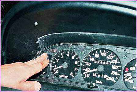
If the diagnostic system determines a malfunction, then, depending on its nature, the lamp may burn (with the ignition on) either constantly or only when the engine is running.
In both the first and second cases, it is necessary to carry out maintenance of the engine control system.
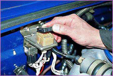
To switch the control unit to the mode for displaying fault codes, turn on the ignition and remove the cover of the diagnostic connector located under the hood.
Use a jumper made of copper wire to connect the terminals "10" and "12" of the connector.
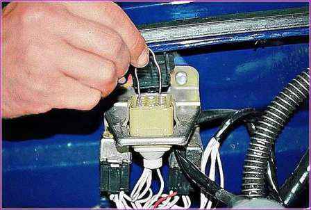
First, the diagnostic system will issue a code (12) three times in a row, indicating the health of the diagnostic circuit, the control circuit and the operability of the diagnostic system.
Fault codes will be displayed next.
Each fault code will be repeated three times
After displaying all fixed fault codes, the information output cycle will repeat. If there are no fault codes in the unit's memory, then only code (12) will appear.
The detected fault code is stored in the unit's memory for approximately two hours.
By the number of activations of the signaling device, we determine the fault codes.
If the battery is disconnected, other setting data generated by the electronic unit to adapt the engine management system to operating conditions will be lost.
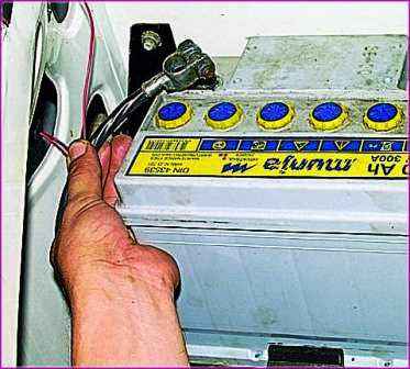
After connecting the ground, start the engine and let it idle (without touching the gas pedal) for at least 1 minute in order to adapt the ignition system to the engine.
To adapt the entire control system, you need to warm up the engine to operating temperature and drive the car for about 1 km with partial throttle opening and without sudden acceleration.
To clear the memory, turn off the ignition and remove the "negative" terminal of the battery for 15 seconds.
Connect the ground terminal to the battery in order to avoid damage to the electronic unit only when the ignition is off.
Fault Code
- Diagnostic Start Mode (Self-Diagnostic Health) 12
- Mass Air Flow Sensor 13 Low
- Mass Air Flow Sensor 14 High
- Air temperature sensor signal low (short circuit) 17
- Air temperature sensor signal high (open circuit) 18
- Coolant sensor signal low (short circuit) 21
- Coolant sensor signal high (open circuit, poor contact in circuit) 22
- Throttle Position Sensor Low (Short Circuit) 23
- Throttle position sensor signal high (open circuit, poor connection in circuit) 24
- Vehicle system low voltage (less than 10V) 25
- High voltage of the vehicle on-board network (more than 18 V) 26
- Low signal level from the corrector (potentiometer) CO 31
- High signal level from the corrector (potentiometer) CO 32
- Malfunction in knock sensor circuit 41
- Control Unit 51 Fault
- Control Unit 52 Malfunction
- Faulty crankshaft position sensor (timing) 53
- 54 Camshaft Position Sensor Malfunction
- Control Unit 61 Malfunction
- Faulty random access memory (RAM. RAM) control unit 62
- Faulty permanent memory (ROM, ROM) control unit 63
- Failure to read block 64 non-volatile memory
- Fault while writing to non-volatile memory 65
- Low frequency in rotation of the crankshaft at idle 71
- High idle speed 72
- Maximum displacement of the PTO* when controlling for detonation in the 1st cylinder 81
- Maximum displacement of the PTO* when controlling for detonation in the 2nd cylinder 82
- Maximum displacement of the PTO* when controlling for knocking in the 3rd cylinder 83
- Maximum displacement of the PTO* when controlling for detonation in the 4th cylinder 84
- Fault in the ignition circuit of the 1st cylinder 91
- Malfunction in the ignition circuit of the 2nd cylinder 92
- Failure in the ignition circuit of the 3rd cylinder 93
- Fault in the ignition circuit of the 4th cylinder 94
- Cylinder 1 injector failure (short circuit) 131
- Cylinder 1 injector failure (open circuit) 132
- Cylinder 1 injector failure (short circuit to housing) 133
- Cylinder 2 injector failure (short circuit) 134
- Cylinder 2 injector failure (open circuit) 135
- Cylinder 2 injector failure (short circuit to housing) 136
- 3rd cylinder injector failure (short circuit) 137
- 3rd cylinder injector failure (open circuit) 138
- 3rd cylinder injector failure (short circuit to housing) 139
- 4th cylinder injector malfunction (short circuit) 141
- 4th cylinder injector malfunction (open circuit) 142
- Cylinder 4 injector failure (short circuit to housing) 143
- WIR 1 winding failure** (short circuit) 161
- Winding fault 1 WFD** (break) 162
- Faulty winding 1 WFD** (short to ground) 163
- Faulty motor winding 2" (short circuit) 164
- Malfunction of winding 2 WFD** (break) 165
- WIR 2 winding failure** (short to ground) 166
- Fuel pump relay circuit malfunction (short circuit) 167
- Fuel pump relay circuit failure (open circuit) 168
- Fuel pump relay circuit failure (short to ground) 169
- Unload relay circuit failure (short circuit)*** 177
- Unload relay circuit failure (open)*** 178
- Unload relay circuit failure (short to ground)*** 179
- Short circuit in warning lamp circuit*** 181
- Indicator lamp open circuit*** 182
- Short to ground in warning lamp circuit*** 183
- * IDO - ignition timing.
- ** RDV - auxiliary air regulator.
- *** Checked by external diagnostic equipment.


