Description of the fuel pump design
The B-9V fuel pump (Fig. 1) is a diaphragm type, driven by an eccentric located on the engine camshaft
The fuel pump consists of prefabricated housing units with a diaphragm 8 and a drive lever 9, a head with valves 4 and 7 and a cover.
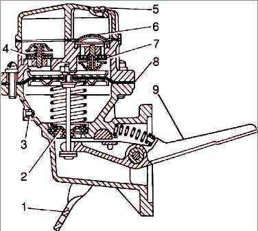
A diaphragm of four petals made of varnished fabric is clamped between the body and the pump head.
The diaphragm rod is sealed with a rubber seal 2.
The valve consists of a cage made of zinc alloy, a rubber valve and a brass plate, pressed by a spring (made of bronze wire).
A filter 6 made of fine brass mesh is installed above the suction valves of the pump.
To fill the carburetor with fuel when the engine is not running, the pump has a device for manual drive.
To control the tightness of the diaphragm in the pump housing there is a hole with a strainer 3.
Removing and disassembling the fuel pump
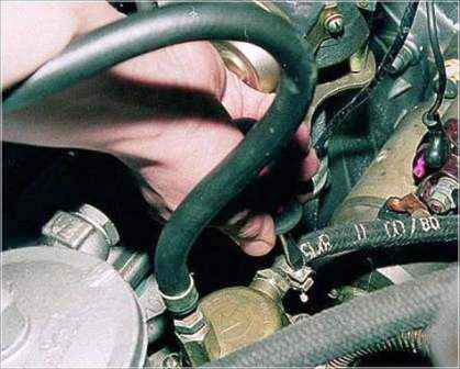
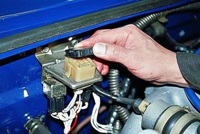
Loosen the clamp and remove the supply hose from the fitting.
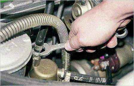
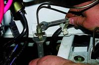
Use the “14” key to unscrew the fitting and disconnect the outlet pipe of the fuel pump.
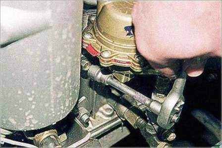
With a 12" head with an extension, unscrew the two bolts.
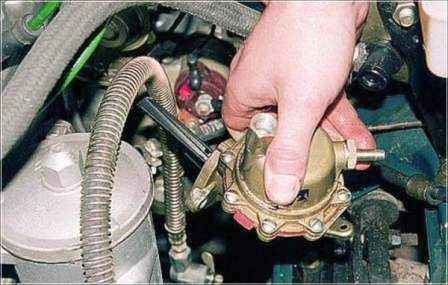
Remove the fuel pump.
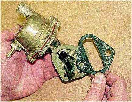
A gasket is installed between the pump and the cylinder block
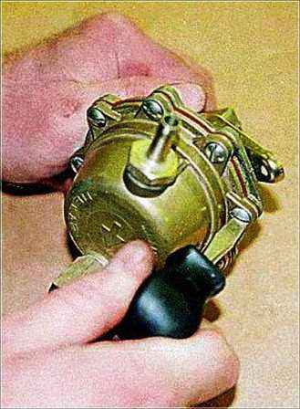
We turn off 8 screws around the perimeter of the pump and remember the position.
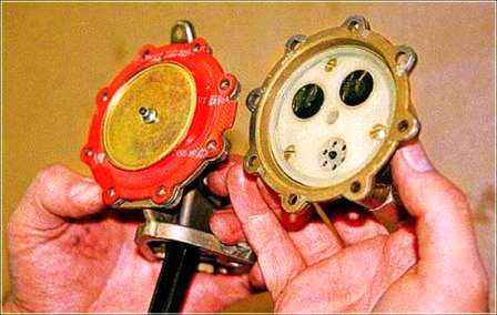
Remove the cover.
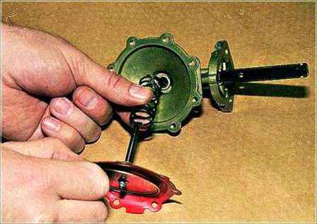
Pressing on the center of the membrane, turn it by 90° and remove the membrane together with the stem and spring.
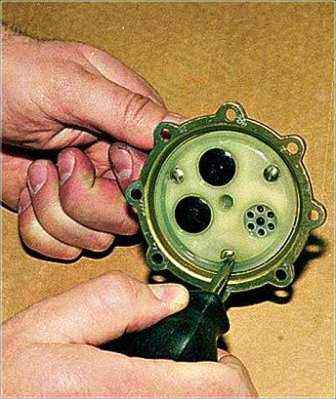
Remove three screws
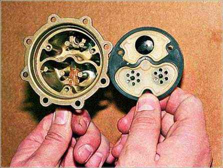
Remove the plastic partition with valves and gasket
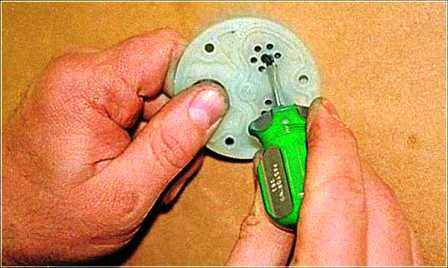
Carefully push the valve stem with a screwdriver.
Remove the valve from the back of the partition.
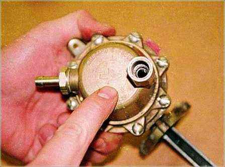
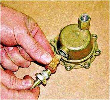
Unscrew the fitting with the “17” key and remove the strainer from it
We assemble the fuel pump in the reverse order.
Orient the pump cover along the arrow indicating the direction of fuel movement
In case of replacing valves, when pressing the clips, it is necessary to ensure the size between the clip and the valve for inlet valves 1.5–1.8 mm, for exhaust valves 2.0–2.3 mm.
When installing the pump head on the housing, tighten the eight fastening screws and, without tightening them, move the manual pumping lever to the upper position and only then finally tighten the screws.


