In this article, we will consider the replacement of sensors in the engine management system
Replacing oxygen sensors
To replace or remove the control oxygen sensor, you will need a special key for 22.
The operations are shown with the engine removed for clarity.
Disconnect the negative battery terminal. We raise the car on a lift.
We press the clamp of the wiring harness block
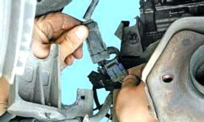
Disconnecting the harness block
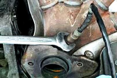
Unscrewing the sensor
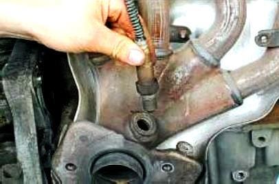
Remove it from the exhaust manifold
To replace the diagnostic oxygen sensor, perform the following operations
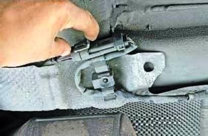
We press the clamp of the wiring harness block
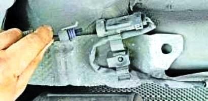
Disconnect the block of the diagnostic oxygen sensor
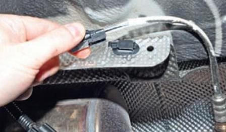
Remove the wiring harness from the holder
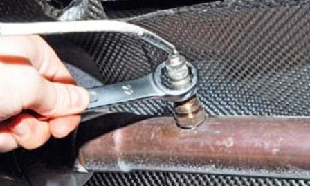
Unscrew the sensor from the hole in the exhaust pipe
Install sensors in reverse order
Torque tighten (45 Nm) the downstream oxygen sensor with a 24 mm socket and the upstream oxygen sensor with tool (Mot. 1495-01).
Removing and installing the accelerator pedal position sensor (all engines)
The position sensor forms one assembly with the accelerator pedal. Together with the sensor, the accelerator pedal must also be replaced.
The car can be equipped with two types of accelerator pedal: with or without a switch at the end of the stroke.
Vehicles equipped with a cruise control/speed limiter are fitted with an accelerator pedal with a switch at the end of the kickdown stroke.
The switch is used to cancel the speed limit mode if the driver needs to increase it.
It is possible to install a pedal with a switch at the end of the stroke instead of a pedal without a switch.
It is forbidden to install a pedal without a switch instead of a pedal with a switch.
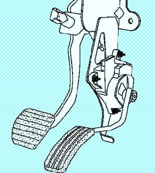
Removing and installing the throttle control pedal
Disconnect the negative battery terminal
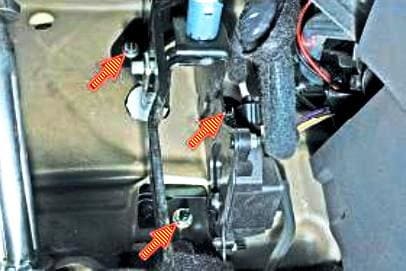
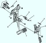
We unscrew the three nuts securing the bracket for the brake and gas pedals
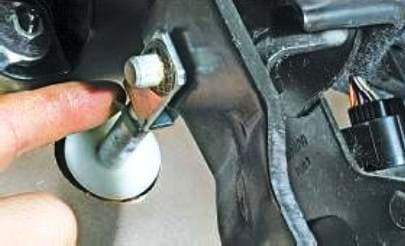
We pry the bracket of the finger of the pusher of the vacuum booster
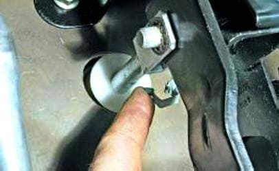
Remove the bracket
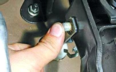
We press the finger out of the holes of the pusher fork of the vacuum booster and the brake pedal
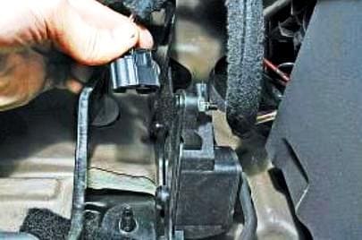
Press the latch, and disconnect the wiring harness connector from the throttle pedal connector
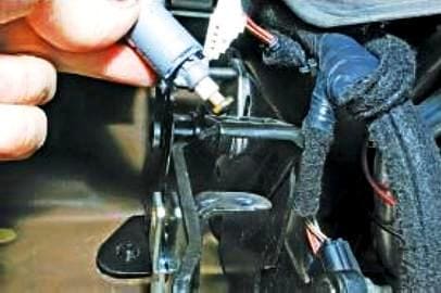
Turn a quarter of a turn and remove the brake light switch
Remove the brake pedal assembly with the throttle pedal
Install in reverse order.
Engine shaft position and speed sensor (all engines)
The sensor is mounted on top of the clutch housing. If a sensor malfunction occurs, the engine stops working.
Before replacing the sensor, disconnect the negative battery terminal.
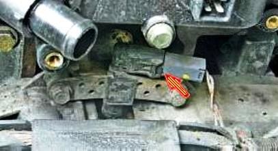
We press the lock of the wiring harness block and disconnect the block from the sensor
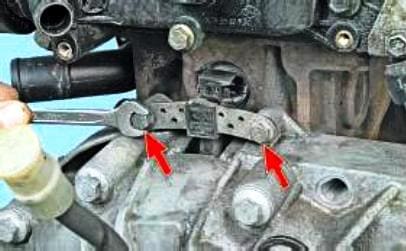
Using a 10 key, we unscrew the two sensor mounting bolts
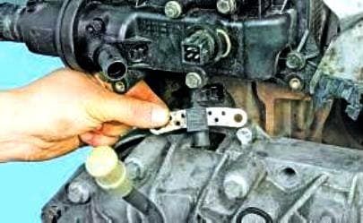
Remove the sensor from the hole in the clutch housing.
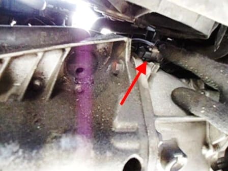
Install the sensor in reverse order.
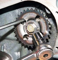
On some models of Renault Megan 2 cars, the crankshaft sensor is located on the side of the clutch housing (Fig. 4). And fastened with one bolt for 6.
To replace or check it, you need to remove the engine protection.
Disconnect the harness block from the sensor and use a 10 key to unscrew the sensor itself.
After replacing the crankshaft position and speed sensor or flywheel, program the target area of the flywheel ring gear.
Perform two successive decelerations in 3rd gear from 4000 rpm-1 until fuel is restored.
Fuel supply will resume when the ECU re-enables fuel injection by reducing the speed with the accelerator pedal released and the fuel supply stopped.
Using a scan tool, check the programming of parameter ET089: Flywheel Target Programming. Read fault codes.
Troubleshoot if necessary.
Clear fault codes from memory. Make sure the car is working.
Removing and installing the petrol injection computer (all engines)
The electronic engine control unit is located under the hood on the left side of the engine, behind the battery.
Use a 10 key to disconnect the negative battery terminal
Remove the cover from the positive battery terminal
Use a 10 key to disconnect the positive battery terminal
Use the T-40 key to unscrew the battery mounting bracket.
Remove the wires and remove the battery
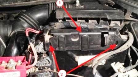
Remove the plastic wire holder.
Take it a little up and to the side.
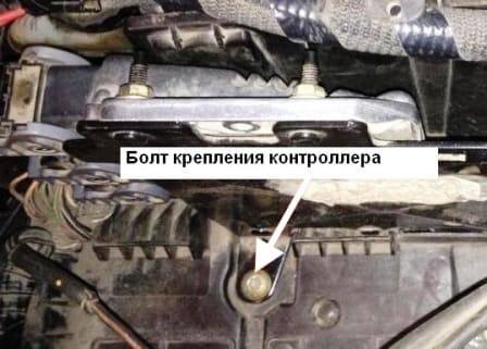
Unscrew the bolt securing the controller bracket to the battery shelf
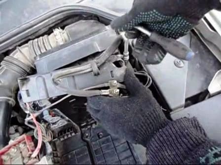
Unscrew the second bracket bolt
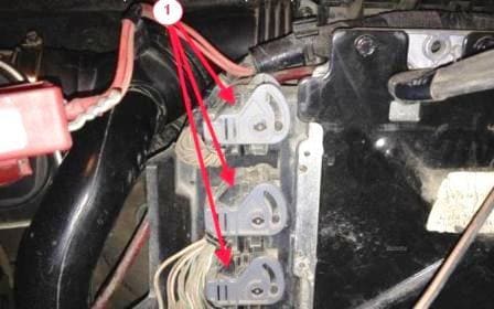
With a slotted screwdriver, press the connector lock and lift the holder, thereby disconnecting the connector, and remove it. Similarly, disconnect two more connectors.
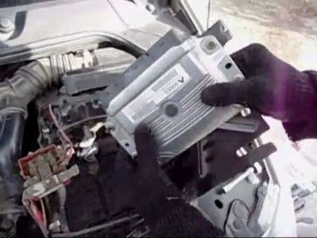
Remove the controller unit together with the bracket.
We unscrew the four bolts securing the controller to the bracket.
Install the computer in reverse order.
You can also watch a video on removing the battery shelf and disconnecting the controller: - removing the controller and battery shelf.
Installation
Installation is performed in the reverse order of removal.
Tighten the battery tray bolts (21 Nm). Connect the wires to the battery terminals, starting with the positive terminal.
When the ignition is turned on, the throttle valve module must cycle through the programming of the minimum and maximum throttle opening angles.
Removing and installing throttle body (k4j engine)
Withdrawal
Disconnect the wires from the battery terminals, starting with the negative terminal.
Remove the air filter housing.
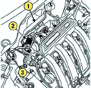
Disconnect the wiring harness from the throttle body and the evaporative emission system hose from the canister purge solenoid valve (fig. 6).
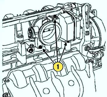
Remove the mounting bolts and remove the throttle body (Fig. 7)
Installation
Installation is performed in the reverse order of removal.
The throttle body gasket must be replaced after each removal (use lubricant to ease installation).
Torque tighten:
- - throttle body mounting bolt (13 Nm);
- - air filter housing mounting bolts (9 Nm).
- Connect the wires to the battery terminals, starting with the positive terminal.
Removing and installing throttle body (k4m engine)
Withdrawal
Disconnect the wires from the battery terminals, starting with the negative terminal.
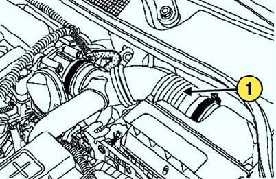
Remove the air duct (fig. 8).
Disconnect the wiring harness from the throttle body and the EVAP hose from the canister purge solenoid valve.
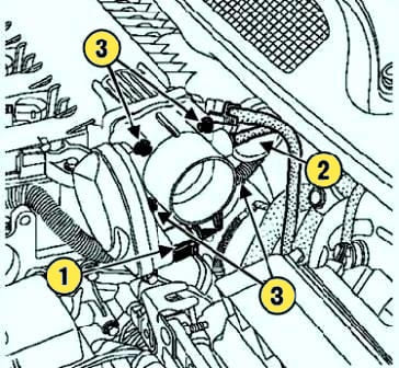
Remove the mounting bolts and remove the throttle body (Fig. 9).
Installation
Replace the gasket every time you remove the throttle body. Installation is made in an order, the return to removal. Tighten the throttle valve bolts evenly to the required torque (13 Nm).
Connect the wires to the battery terminals, starting with the positive terminal.
Removing and installing throttle body (f4r engine)
Remove the negative terminal from the battery.
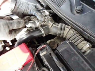
Use a slotted screwdriver to loosen the clamp securing the air duct to the throttle assembly
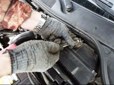
Loosen the clamp securing the air duct to the air filter housing.
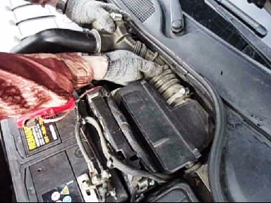
Remove the duct.
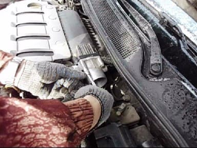
Using a 10 key, we unscrew the four bolts securing the throttle assembly
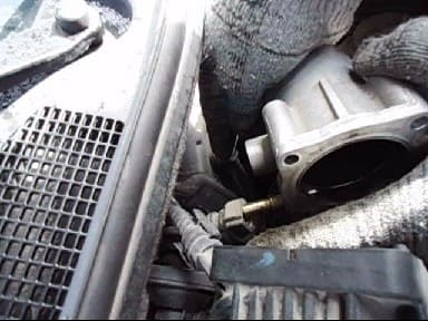
Disconnecting the recirculation tube
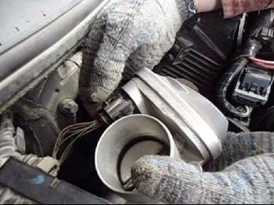
Press the latch with a thin screwdriver and remove the throttle control connector
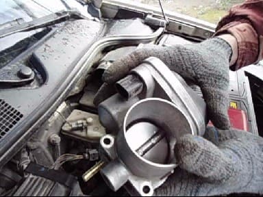
Remove the throttle assembly for cleaning
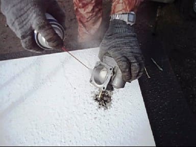
Clean the throttle assembly with carburetor cleaner.
Blow out the throttle assembly with compressed air
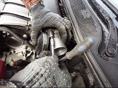
Install the throttle assembly in reverse order
When installing, check the rubber sealing ring.
Replace the gasket every time you remove the throttle body. Installation is carried out in the reverse order of removal.
Torque tighten (10 Nm) the throttle valve mounting bolts (F4R 776 engine).
Tighten the throttle valve bolts evenly to the specified torque (13 Nm).
Connect the wires to the battery terminals, starting with the positive terminal.


