Gearbox - mechanical, with manual shifting, has five forward gears and one reverse gear, all forward gears are synchronized
The body parts of the box - the clutch housing, the gearbox housing itself and the rear cover - are cast from an aluminum alloy and tightened together with studs and nuts.
The joints are sealed with cardboard gaskets (sealant can be used for repairs). To improve heat dissipation, the surface of the gearbox housing is finned.
The bottom of the crankcase is closed with a stamped steel cover with a gasket (mounted on studs).
The clutch housing is bolted to the engine block.
To ensure the alignment of the crankshaft and the input shaft of the gearbox, the crankcase is centered on two bushings (grooves are made under them in the mounting holes of the block and crankcase).
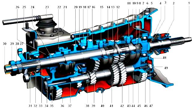
Gearbox BA3-2123: 1 - input shaft; 2 - clutch release clutch; 3 - front cover with guide sleeve; 4 - input shaft seal; 5 - clutch housing; 6 - breather; 7 - gearbox housing; 8 - gear wheel of constant engagement of the input shaft; 9 - needle bearing of the secondary shaft; 10 - tray for collecting and draining oil; 11 - synchronizer of III and IV gears; 12 - third gear gear; 13 - gear wheel of the 2nd gear; 14 - secondary shaft; 15 - synchronizer of I and II gears; 16 - gear 1st gear; 17 - bushing gear 1st gear; 18 - intermediate bearing of the secondary shaft; 19 - lock plate of the intermediate bearing; 20 - reverse gear; 21 - nut for fastening the gear selection mechanism; 22 - synchronizer V transmission; 23 - gear selection mechanism; 24 - gear V gear; 25 - bracket for fastening the base plate; 26 - oil slinger; 27 - flange of the flexible coupling of the driveline; 28 - nut; 29 - centering ring seal; 30 - centering ring; 31 - output shaft seal; 32 - rear bearing of the secondary shaft; 33 - spacer sleeve; 34 - gear block bolt; 35 - gear block bearing; 36 - rear cover of the gearbox; 37 - gear block of V gear and reverse gear; 38 - rear bearing of the intermediate shaft; 39 - gear of the 1st gear of the intermediate shaft; 40 - drain plug; 41 - gear wheel of the second gear of the intermediate shaft; 42 - gear wheel of the III gear of the intermediate shaft; 43 - lower cover of the gearbox; 44 - intermediate shaft; 45 - gear wheel of constant engagement of the intermediate shaft; 46 - front bearing of the intermediate shaft; 47 - clamping washer of the bearing of the intermediate shaft; 48 - clamping washer bolt; 49 - input shaft rear bearing
A third power unit support is installed on the rear cover of the gearbox. It is attached to the cross member, and the latter to the floor of the body (on welded bolts).
There is a filler (control) hole in the gearbox housing on the left side, and a drain hole in its lower cover.
The holes are closed with tapered plugs. There is a magnet in the drain plug. It traps steel particles that enter the oil when parts are worn.
A breather is screwed into the top of the clutch housing. It prevents the increase in pressure in the gearbox when it is heated.
In the event of a breather malfunction (jamming of the cap), severe oil leakage through the seals is possible. There are three shafts in the gearbox: primary, secondary and intermediate.
The input shaft rests on two ball bearings - in the rear end of the crankshaft and in the front wall of the gearbox housing (the latter takes the bulk of the load).
A needle bearing is installed at the rear end of the input shaft, which is the front support of the secondary shaft and ensures the alignment of the shafts.
The output shaft also rests on a ball bearing in the rear wall of the gearbox housing and a roller bearing in its rear cover.
The intermediate shaft rotates in two bearings: the front one is a double-row ball bearing, located in the front wall of the gearbox housing, the rear one is roller, located in its rear wall.
Through the reverse gear and V gear, the intermediate shaft also rests on a roller bearing in the rear cover of the gearbox. On the rear wall of the crankcase, the axis of the reverse intermediate gear is also fixed.
The input shaft has two gears.
The helical ring, located closer to the front wall of the crankcase, is in constant engagement with the front gear of the countershaft (thus, these shafts always rotate together).
The spur gear of the input shaft is the crown of the IV gear synchronizer (when it is turned on, the torque is transmitted directly from the input shaft to the secondary, bypassing the intermediate one, therefore this gear is often called "direct").
the terrible shaft is a block of four helical gears. When you turn on any gear other than IV, the torque is transmitted to the secondary shaft through the intermediate.
The gears of the intermediate shaft are located in the following order (from its front end): gear of constant engagement with the input shaft, gears of III, II, I gears.
A block of two gears is bolted to the rear end of the shaft: reverse gear (spur gear) and V gear (helical gear).
It additionally relies on a roller bearing in the rear cover of the gearbox.
On the secondary shaft there are driven gears of III, II, I gears, reverse and V gears (in order, counting from the front end of the shaft) and synchronizers.
The driven gears of the forward gears are in constant mesh with the corresponding countershaft gears.
The gears of III and II gears rotate on hardened journals of the secondary shaft, the gears of I and V gears - on bushings.
The reverse driven gear is rigidly keyed to the shaft.
Along with the helical gears of the forward gears, the rims of their synchronizers are made - spur gears of a smaller diameter.
They are directed towards the corresponding synchronizer (III, I, V - forward, II - back). At the rear end of the secondary shaft, a flange of an elastic coupling is fixed with a nut.
Earlier, the nut was fixed from unscrewing by a lock washer placed under it - its edges were bent on the edge of the nut.
Anaerobic sealant is now applied to the threads, and the washer is not installed.
The synchronizer consists of a hub rigidly fixed to the output shaft, a sliding sleeve, a retaining ring, a blocking ring and a spring with a washer.
The hubs of the synchronizers of III-IV and I-II gears enter the grooves on the secondary shaft with internal projections, and the hub of the synchronizer of the V gear is held by the same key as the reverse driven gear.
On the outer surface of the hubs there are slots along which the sliding sleeves move. The clutches have grooves that include the forks of the gearshift rods.
The locking rings are connected with their inner rims to the synchronizer rims of the corresponding gears and are pressed by springs towards the sliding clutches.
The springs rest on the side surface of the driven gears through washers. The reverse gear does not have a synchronizer.
To turn it on, you need to enter the intermediate gear into engagement with the output shaft driven gear and with the reverse drive gear in the rear gear block on the intermediate shaft.
The gearbox control drive consists of three rods connected to forks.
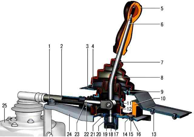
Drive for controlling the gearshift mechanism: 1 - nut for fastening the base plate; 2 - thrust of the gearbox control drive; 3 - manhole cover gasket; 4 - hatch cover of the gear lever; 5 - lever handle; 6 - gear lever; 7 - a cover of the gear lever; 8 - sealing case; 9 - screw securing the hatch cover; 10 - rear support; 11 - gear lever housing; 12 - lower housing of the gear lever; 13 - nuts for fastening the rear support; 14 - rear support washer; 15 - nut; 16 - spacer ring; 17 - retaining ring; 18 - body of the ball bearing; 19 - spring of the gear lever; 20 - ball bearing slider; 21 - nuts for fastening the body of the ball joint; 22 - protective cover; 23 - thrust tip; 24 - support plate; 25 - gearbox
The forward gear forks fit into the undercuts of the synchronizer sliding sleeves, and the reverse gear fork into the undercut on the intermediate gear.
The gear selector mechanism consists of a guide plate with eight rectangular cutouts in the center, upper and lower washers, a gear lever and its housing, and a reverse locking bracket.
These parts are tightened with three bolts that secure the gear selector mechanism to the rear cover of the box.
The "neutral" position of the lever between III and IV gears is set by two pairs of spring-loaded guide bars installed in the grooves of the guide plate and acting on the lower end of the lever.
Inadvertent engagement of reverse gear instead of V gear is impossible due to the bent tab of the locking bracket against which the protrusion on the lever rests.
To engage reverse gear, you need to push the lever down - while its protrusion falls below the tab of the bracket.
Gearbox parts are splash lubricated.
The primary and secondary shafts are sealed with oil seals, and on the secondary shaft behind the driven gear of the 5th gear there is an oil slinger.
The gearbox is filled with gear oil with a viscosity of 75W80 to 85W90 and a quality class of at least GL-4. His uro The wedge should be at the lower edge of the filler hole (make sure that the car is level beforehand).
Gearbox fault diagnosis
- Cause of malfunction
Remedy
Noise in the gearbox. The noise decreases or disappears when the clutch is depressed
The transfer case is in neutral
- Insufficient oil level in the gearbox housing
- Check the level, add oil if necessary.
- Check for leaks.
- Clean the breather
- Wear or damage to bearings, gear teeth
Replace worn bearings, gears
- Gearbox shafts move axially
Tighten nuts, replace broken fixing parts
Gears are difficult to turn on, there are no extraneous noises
- Gearbox oil too thick
Use oil according to climatic conditions
- Wear or deformation of the gear lever
Correct or replace lever
Spherical joint sticking of the gear lever
Replace the deformed parts, put lubricant LSTs-15, Litol-24 or SHRUS-4 into the hinge
- The stems of the forks are tight (blocking crackers are jammed, burrs on the stems, dirt in the sockets)
Clean worn and deformed parts - replace
- The sliding clutch moves tight on the splines of the hub
Clean the splines from dirt, cut off the burrs with a needle file, replace parts with wrinkled splines
- Deformed shift forks
Replace forks
Transmissions spontaneously turn off
- The springs of the clamps have lost their elasticity, the balls and / or the sockets of the rods are worn out
Replace worn parts
- Damage or wear of the synchronizer blocking rings
Replace rings
- Damage or wear of the teeth of the coupling or the ring gear of the synchronizer
Replace clutch or gear
- Broken synchronizer spring
Replace the spring
Noise, crackle, squeal of gears at the moment of switching on the gear
Low oil in the gearbox housing
- Add oil.
- Check for leaks.
Clean or replace breather
- Wear or breakage of gear teeth and / or synchronizers
Replace Parts
- Wear or deformation of the gear synchronizer ring
Replace the ring
- Axial play of gearbox shafts
Tighten bearing mounts, replace worn bearings
Oil leak
- Wear of oil seals
Replace the oil seals.
Clean or replace transmission breather if necessary
- Strong wear, nicks on the surfaces of the shafts on which the seals work
Remove minor damage with fine-grained sandpaper and polish.
Installing a new stuffing box, you can slightly underpress it, avoiding distortion (if necessary, placing spacers up to 1 mm thick under it) so that the edge of the stuffing box works on the unworn part of the shaft.
In case of significant damage, replace the shafts and seals
- Increased pressure in the gearbox due to clogged breather
Clean or replace transmission breather
- The fastenings of the covers of the gearbox housing, clutch housing have loosened. Gasket damage
Tighten the screw connections.
Replace the gaskets (sealant may be used when installing them)
- The corks are loose
Tighten the plugs (you can put them on the sealant)


