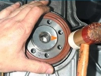
We remove the steering knuckle when repairing the front suspension strut
Remove
To avoid damage to the front wheel hub bearing is not allowed:
- - loosen and tighten the nut of the front wheel hub on the car standing on wheels;
- - lower the car on the wheels with the front wheel drive shaft removed or with the front wheel hub fastening nut loosened.
Put the car on a lift.
Unlock the steering wheel.
Remove the front wheel.
Remove the front wheel speed sensor;
Disconnect the front brake assembly from the steering knuckle and hang it from the front suspension spring.
Install a stop on the front wheel hub and secure it with two wheel bolts (stop Rou. 604-01, interchangeable head 17, knob).
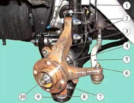
Removing the steering knuckle: 1 - telescopic front suspension strut; 2 - nuts of the bolts for fastening the steering knuckle to the front suspension strut; 3 - rotary fist; 4 - front wheel speed sensor; 5 - outer tip of the steering rod; 6 - nut for fastening the tie rod end to the steering knuckle; 7- nut of a bolt of fastening of a spherical support to a rotary fist; 8 - ball bearing of the front suspension arm; 9 - front suspension arm; 10 - front wheel hub nut
Unscrew the nut 10, figure 1, fastening the front wheel hub, remove the nut, remove the stop (replaceable head 32, interchangeable head 17, knob).
Remove the front brake disc;
Remove the front brake disc cover.
Disconnect the tie rod end from the knuckle arm.
Unscrew the nut 7 of the bolt securing the ball joint of the front suspension arm to the steering knuckle and disconnect the knuckle 3 from the lever 9 (ring key 16, interchangeable head 16, extension and knob).
Remove the spacer from the front suspension arm ball joint.
Unscrew the two nuts 2 of the bolts securing the steering knuckle to the front suspension strut and remove the bots (wrench 18, interchangeable head 18, knob).
Press the drive shaft out of the front wheel hub and remove the steering knuckle with hub assembly.
Installation
Attention. The fasteners listed below must be replaced:
- - front wheel hub nut;
- - nut of the front suspension arm ball joint bolt;
- - nuts of the bolts of the steering knuckle to the front suspension strut.
Attention. Install the ball joint bolt of the lower front suspension arm to the steering knuckle with the head towards the front of the vehicle.
Install the spline shank of the front wheel drive shaft into the front wheel hub.
Install the steering knuckle on the front suspension strut, insert the mounting bolts and tighten, without tightening, new nuts 2 (wrench 18, interchangeable head 18, ratchet wrench).
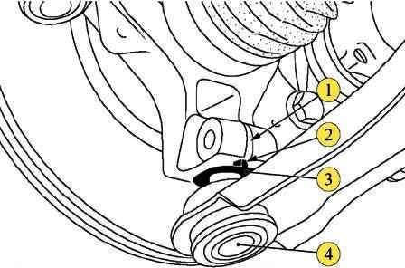
Installation of the spacer washer: 1 - slot of the terminal connection of the steering knuckle and ball joint; 2 - a shoulder of a remote washer; 3 - remote washer; 4 - ball joint of the front suspension arm
Install the spacer washer 3 on the ball joint pin 4, figure 2, of the front suspension arm.
Install the ball joint pin of the front suspension arm into the steering knuckle, install the mounting bolt and tighten the new nut.
When assembling, the shoulder 2 of the spacer 3 must fit into the slot 1 of the terminal connection on the steering knuckle.
Nut tightening torque 62 Nm (6.2 kgf.m) (wrench 16, interchangeable head 16, ratchet wrench, torque wrench).
Tighten the nuts of the bolts securing the steering knuckle to the front suspension strut.
Nut tightening torque 105 Nm (10.5 kgf.m) (wrench 18, interchangeable head 18, torque wrench)
Connect the tie rod end to the knuckle arm.
- - install front brake disc cover;
- - install front brake disc.
Install a stop on the front wheel hub and secure it with two wheel bolts.
Tighten the new front wheel hub nut and remove the stop.
Nut tightening torque 280 Nm (28.0 kgf.m) (replaceable head 17, interchangeable head 32, knob, torque wrench).
- - set the front wheel speed sensor;
- - install front brake assembly.
Install the front wheel. Press the brake pedal 2-3 times for setting the pistons of the wheel brake cylinders to the working position.
Check and, if necessary, adjust the alignment of the front wheels.


