KIA RIO engine control sensors
Ignition timing
Apply the parking brake.
Start the engine and warm it up to operating temperature.
Turn off all electrical consumers.
Connect the strobe sensor to the high voltage wire of the first cylinder.
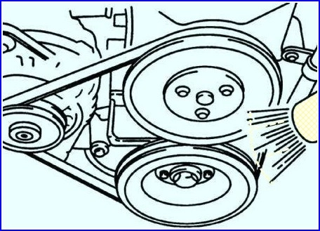
Check the ignition timing by aligning the marks on the crankshaft pulley with the pointer on the timing belt housing.
Ignition timing:
- 8±5° BTDC (at idle speed)
- (6±5° BTDC: A5D engine for Europe)
The ignition timing is not adjustable.
If the ignition timing is not within the specified range, replace the ECM.
Idle speed
Apply the parking brake.
Start the engine and warm it up to operating temperature.
Turn off all electrical consumers.
Connect an inductive tachometer to the high voltage wire of the first cylinder or to the "O" terminal of the diagnostic connector (DLC).
Idle speed is not adjustable.
The idle speed is automatically controlled by the ECM.
Varying idle speed can be caused by a malfunctioning idle speed control (IAC) valve or intake manifold leaks.
With the shift lever in neutral, measure the idle speed.
Idle speed (gearbox in neutral): 750±50 min–1
Due to the "wasted" ignition spark, some tachometers will show RPM twice the actual speed.
Disconnect the tachometer from the high voltage wire or the "O" terminal of the diagnostic connector (DLC).
Turn off the engine.
Knock sensor
Check
Disconnect the knock sensor electrical connector and remove the knock sensor.
Clamp the knock sensor in a vise and connect a voltmeter between terminals 1 and 2.
Sharply hit the vise with a hammer and observe the readings of the voltmeter.
Check that the knock sensor is outputting peak voltage (less than 1V).
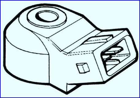
If there is no peak voltage, replace the knock sensor.
Withdrawal:
- 1. Remove the intake manifold support bracket.
- 2. Disconnect the knock sensor harness.
- 3. Unscrew the bolt and remove the knock sensor.
Installation:
- 1. Install the knock sensor and secure it with the bolt.
- 2. Install the knock sensor harness.
- 3. Install the intake manifold support bracket.
Throttle position sensor
Resistance test:
Disconnect the connector from the throttle position sensor.
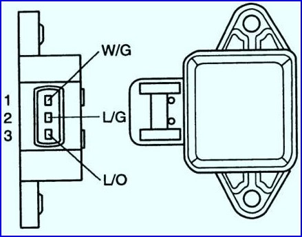
Connect an ohmmeter between pins 1 and 2 of the connector.
Check that the resistance of the sensor increases in proportion to the throttle angle.
Resistance: 1.6-2.4 kΩ at closed throttle
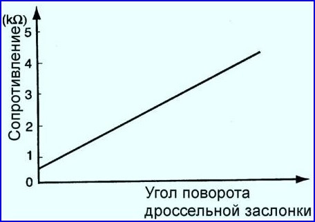
If the sensor resistance is out of specification, replace it.
Connect the connector to the sensor.
Voltage test
- 1. Check that the throttle is fully closed.
- 2. Turn on the ignition without starting the engine.
- 3. Connect a voltmeter to pins 2 (wire L/G - light/green) and 1 (wire W/G - white/green) of the throttle position sensor connector. The voltmeter should show a voltage of 5 V.
- 4. Connect a voltmeter to pins 3 (wire L/O - light/orange) and 1 (wire W/G - white/green) of the throttle position sensor connector.

- 5. Measure voltage with fully open and fully closed indoor throttle position.
Voltage at full throttle: 0.2-0.8V
Voltage at wide open throttle: 4.0-4.8V
- 6. If the voltage is out of specification, replace the throttle position sensor.


