Drive shafts transmit torque from the engine, gearbox and differential to the front wheels
In the gearbox housing, the drive shafts are splined to the side gears of the differential
Fixation of the splined tip of the internal joint of the drive shaft in the side gear is carried out by means of a spring retaining ring.
When installed, the circlip compresses into the shaft groove.
After the shaft is fully installed in the differential side gear, the retaining ring is released and fixes the splined tip from axial movement.

Front wheel drives: A - right front wheel drive; B - left front wheel drive; 1 - threaded part of the tip of the outer hinge; 2 - slotted tip of the outer hinge housing; 3 - body of the outer hinge of equal angular velocities; 4 - a large clamp for fastening the hinge cover; 5 - hinge cover; 6 — a small collar of fastening of a cover of the hinge; 7 - drive shaft of the right front wheel; 8 - body of the internal hinge of equal angular velocities; 9 - intermediate shaft support; 10 - intermediate shaft; 11 - splined tip of the intermediate shaft; 12 - retaining ring; 13 - drive shaft of the left front wheel; 14 - threaded part of the tip of the inner hinge
The outer joints of the drive shafts are attached to the front wheel hubs mounted on bearings.

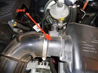
External constant-velocity hinge: 1 - clamps for fastening the cover; 2 - three-stud hub; 3 - roller; 4 - toothed disk of the ABS sensor (in the presence of ABS); 5 - hinge body; 6 - spring; 7 - adjusting spacer; 8 - pusher; 9 - drive shaft; 10 - hinge cover
The outer hinge consists of a body 5 (Fig. 2) and three rollers 3, put on the trunnions of a three-pin hub 2.
The hub is made in one piece with the hinge body.
The rollers enter the grooves of the hinge cage, made in one piece with the drive shaft 9.
This design allows the hinge to rotate to the required angle.
The splined shank of the outer joint housing is secured to the front wheel hub with a nut.
The sealing of the hinge is provided by a cover 10, fixed with clamps 1 on the hinge body and on the drive shaft.
For the repair of the external hinge, only its cover and cover fastening clamps are supplied as spare parts.
In case of failure, the hinge must be replaced as an assembly with the drive shaft, since the hinge cage forms a non-separable unit with the shaft.

Right internal CV joint: 1 - retaining ring; 2 - hinge body; 3 — a roller of a three-spike hub; 4 - clamps for fastening the cover; 5 - hinge cover
The right inner hinge consists of a body 2 (Fig. 3) and three rollers 3 on needle bearings, put on the trunnions of a three-spike hub.
Slots for rollers are made in the hinge body.
The three-spike hub is fixed on the drive shaft with a retaining ring 1, the rollers allow the hub to move in the grooves of the hinge body in the axial direction, so that the drive can lengthen or shorten to compensate for the mutual movements of the suspension and the power unit.
The tip of the internal joint housing with internal splines is put on the splined shank of the right side gear.
After axial movement on the pinion shank during suspension operation, the hinge body is fixed by an expanding spring installed inside the hinge.
The sealing of the hinge is provided by a cover 5, fixed with clamps 4 on the hinge body and on the drive shaft.
In the gearbox housing, the tip of the hinge housing is sealed with a toroidal rubber ring and a self-compressing oil seal.
To repair the right inner hinge, two repair kits are supplied as spare parts: a large one, which includes all the hinge parts, and a small one, similar to the outer hinge repair kit.

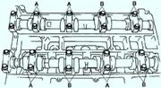
Left inner CV joint growths: 1 - mud deflector; 2 - stuffing box; 3 - bearing; 4 - case holder; 5 - hinge cover; 6 - roller of a three-spike hub; 7 - retaining ring; 8 - drive shaft
The left inner hinge consists of three rollers 6 (Fig. 4) on needle bearings, put on the trunnions of a three-spike hub.
The function of the hinge housing is performed by the left semi-axial gear of the gearbox of complex shape.
Its internal grooves for the rollers are made similar to the grooves of the body 2 (see Fig. 3) of the right inner hinge.
The three-spike hub is fixed on the shaft 8 (see Fig. 4) of the drive with a retaining ring 7.
The rollers allow the hub to move in the slots of the side gear in the axial direction, so that the drive can be extended or shortened to compensate for the mutual movements of the suspension and the power unit.
The sealing of the hinge is provided by a cover 5, which is fixedly fixed with the help of a holder 4 on the gearbox housing.
The drive shaft rotating inside the case in bearing 3 is sealed with gland 2 installed under the case in a removable unit common with the bearing.
To repair the left inner joint, two repair kits are supplied as spare parts: a large one, which includes all parts of the joint, except for the side gear, and a small one, including the joint case and the bearing assembly with the oil seal.
The shaft is attached to the hub with a nut.
On the differential side of the drive shaft, a tripoid-type universal constant velocity joint (CV joint) is installed, providing a low level of vibration.
The CV joints are protected by rubber covers, which are fastened with clamps and protect against water and dirt.
Cases should be inspected periodically for signs of damage, lubricant leaks, or cuts.
Damaged CV joints must be replaced immediately with new ones, otherwise the CV joints may be damaged.
Replacing the boot includes the operation of removing the drive shafts.
Signs of worn or damaged CV joints, in addition to lubrication leaks, are clicks when driving and cornering, hum when accelerating after coasting, or vibration at high speeds on the highway.
Wheel drive shafts for jr, jh, nd, dp0 manual transmissions

")
")
")
")
")
")