Electronic control unit with 128 contacts
SAGEM brand S3000 manages injection and ignition systems and has multipoint sequential injection (F4R, K4J engines)
There is no TDC sensor for the piston of the first cylinder on the camshaft, therefore, synchronization of the control of the system elements with the engine working process is carried out according to the program using the TDC sensor signals.
The engine is started in a semi-sequential mode (to synchronize the control of the system elements with the engine workflow), then it switches to a sequential synchronized mode.
K4M engines are equipped with a TDC sensor for the first cylinder on the camshaft.
Synchronization of the control of the elements of the system with the working process of the engine (determination of the TDC of the piston of the 1st cylinder) is carried out according to the signal of this sensor.
The engine starts in a semi-sequential mode (to synchronize the control of the system elements with the engine workflow), then it switches to a sequential synchronized mode.
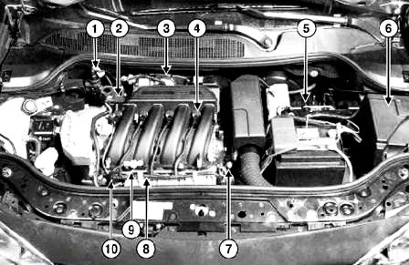
Fig. Fig. 1. Location of the injection system elements in the engine compartment of a Megane II car with a K4J engine: 1 - fuel vapor recirculation solenoid valve: 2 - absolute pressure sensor; 3 - throttle valve block with a servo drive; 4 - ignition coil; 5 - ECU of the injection system; 6 - block of protection and switching; 7 - coolant temperature sensor: 8 - knock sensor; 9 - air temperature sensor; 10 - ramp and nozzles
Injection system warning light on instrument panel active
Using a dedicated injection system warning light (OBD "On-Board Diagnostic" warning light).
Its presence is due to the installation of an "on-board diagnostic system".
Special precautions regarding the immobilizer system
Due to the installation of a third-generation electronic anti-theft engine immobilizer system, the ECU is replaced using a special technique.
Fuel supply system without fuel return to the fuel tank
The pressure regulator is located in the "fuel pump - fuel level sensor" assembly. Idle mode (hot engine).
Rated idle speed
The idling mode is adjusted depending on: – Coolant temperature; – battery voltage;
- – air conditioner status (on/off);
- - oil pressure (automobile with K4M engine);
- – automatic transmission selector lever position (car with F4R engine).
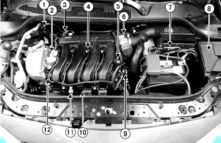
Fig. Fig. 2. Location of injection system elements in the engine compartment of a Megane II car with a K4M engine: 1 - fuel vapor recirculation solenoid valve; 2 - solenoid valve of the camshaft dephaser: 3 - absolute pressure sensor; 4 - ignition coil; 5 - camshaft position sensor; 6 - throttle valve with servo; 7 - ECU of the injection system; 8 - block of protection and switching; 9 - coolant temperature sensor; 10 - knock sensor; 11 - air temperature sensor; 12 - ramp and nozzles
Maximum crankshaft speed
Protection in case of exceeding the maximum permissible engine speed of the crankshaft of a cold K4J engine.
If the coolant temperature is below 60°C, or within 10 seconds after starting the engine, the fuel supply is cut off at 5800 min–1.
K4M
If the coolant temperature is below 75°C, or within 10 seconds after starting the engine, the fuel supply is cut off at 5800 min–1.
F4R
If the coolant temperature is below 75°С, or within 17 seconds after starting the engine, the fuel supply is cut off at 5900 min–1.
Protection in case of exceeding the maximum permissible engine speed of the crankshaft of a hot engine
If the engine is hot, this value returns to its normal value.
K4J and K4M
Fuel supply stops at 6500 min–1 regardless of the gear selected (manual or automatic transmission).
F4R
Fuel supply is cut off at 6000 min–1 regardless of the gear engaged (manual transmission) and 6300 min–1 (automaticth gearbox).
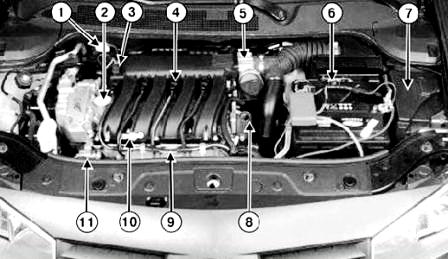
Fig. Fig. 3. Location of injection system elements in the engine compartment of a Megane II car with an F4R engine: 1 - fuel vapor recirculation solenoid valve; 2 - solenoid valve of the camshaft phase regulator; 3 - absolute pressure sensor; 4 - ignition coil; 5 - throttle valve block with a servo drive; 6 - ECU of the injection system; 7 - protection and switching unit: 8 - coolant temperature sensor: 9 - knock sensor; 10 - air temperature sensor; 11 - ramp and nozzles
K4M camshaft phase regulator
The valve timing smoothly changes from 0 to 43 ° according to the angle of rotation of the crankshaft.
The phase regulator is controlled by a solenoid valve, which is energized in the form of a variable signal of the degree of cyclic opening from the injection computer.
F4R
The phase regulator is a solenoid valve that is powered on a yes-no basis by the injection computer.
Control of the electric fan of the engine cooling system and the signal lamp for the emergency temperature of the coolant.
The request comes from the injection computer via the multiplex network (central coolant temperature control function).
Power supply is supplied to the electric fan from the protection and switching unit.
A/C compressor control
The request comes from the injection computer via the multiplex network.
The request is generated based on data on the operation of the air conditioner, as well as taking into account the temperature of the coolant.
The air conditioning compressor is powered by the protection and switching unit.
Fuel pump control
The request comes from the injection computer. The supply voltage is supplied to the fuel pump from the protection and switching unit.
Regulator - limiter
The speed limiter and the air conditioning system are configured automatically.
Oxygen sensor
Using two oxygen sensors installed at the inlet and outlet of the catalytic converter.
Throttle body
Air supply and idle speed are controlled by a motorized throttle valve.
Protection and switching unit
The unit supplies power to the following units:
- – ignition coils;
- - fuel pump;
- – air conditioning compressor;
- – electric fan;
- - some actuators of the injection system (injectors, canister purge solenoid valve, etc.).
- The protection and switching unit is located in the engine compartment next to the battery.
The unit provides protection for the circuits of some electrical appliances.
To perform this function, the unit includes fuses and several built-in relays:
- - relay "+" after the ignition switch";
- - fuel pump relay;
- - air conditioner compressor relay;
- - relay for the electric fan of the engine cooling system;
- – starter relay (starter traction relay control).
These relays are non-removable.
Injection ECU
The unit constantly receives information about the electrical power generated by the generator via the multiplex network.
This is necessary so that the electricity consumption of the car does not exceed the capacity of the generator.
The main task is to ensure that the battery is charged.
Accelerator pedal
Replacing the accelerator pedal is easy.
The ECU takes the value read when the ignition was switched on as the pedal released reference.
The sensor, made in the form of a two-track potentiometer, provides information to the computer about the position of the accelerator pedal.
The signal voltage from the sensor has two conductive paths with different resistance.
Trace 1 delivers a voltage (0-5V) that is twice the signal voltage from trace 2 (0-2.5V).
Comparing the voltage of both signals allows you to make sure that the generated signal corresponds to the current value.
Idle mode
The idle speed will increase by no more than 160 min-1 if the battery voltage is below 12.7 V.
In the event of a present and stored MAP sensor fault, the idle speed setpoint is set to:
- -896 min-1 (K4J and K4M engines),
- -1024 min-1 (F4R engine).
The S 3000 injection system controls the activation of three signal lamps and the display of messages according to the stagenew severity of detected malfunctions in order to determine the necessary diagnostics.
The injection computer controls the warning lights and messages on the instrument panel.
These warning lights come on during the starting phase of the engine, as well as in the event of a malfunction in the injection system or overheating of the engine.
Commands to turn on signal lamps are transmitted to the instrument panel via the multiplex network.
PRINCIPLE OF OPERATION OF SIGNAL LIGHTS
When starting the engine by pressing the start button.
The "On-Board Diagnostic" warning light comes on for about 3 seconds and then goes out.
In the event of a malfunction of the injection system (1st degree of severity)
The written message "injection a controle" (check the injection system) is displayed, accompanied by the "service" warning light.
This indicates a decrease in safety and the need to use the engine in a "sparing" mode.
The owner must rectify the faults as soon as possible.
The cause of these malfunctions can be:
- - malfunction of the throttle valve with a servo;
- - malfunction of the accelerator pedal position sensor;
- – malfunction of the absolute pressure sensor;
- - ECU malfunction;
- - malfunctions in the power supply circuits of actuators;
- - malfunctions in the power supply circuit of the computer.
In the event of a serious malfunction of the injection system (2nd degree of severity)
The red engine symbol and the message "stop" (dot matrix display only) are illuminated and the written message "mjection defaillante" (injection system defective) appears, accompanied by the "stop" warning light and an audible signal.
When the engine overheats
The engine temperature warning symbol appears (dot matrix display only) with the written message "surchauffe moteur" (engine overheating), accompanied by the "stop" warning light and an audible signal.
In this case, stop driving immediately.
If a malfunction is detected that leads to excess of exhaust gas toxicity standards.
The "On-Board Diagnostic" warning light comes on with the engine symbol:
- - "flashing light" in case of a malfunction that can lead to the destruction of the catalytic converter (misfire of the mixture leading to its destruction).
In this case, stop driving immediately.
- - “constant light” in case of exceeding the exhaust gas toxicity standards (during misfires of the mixture, leading to an increase in toxicity, a malfunction of the catalytic converter, a malfunction of the oxygen sensors, a discrepancy between the signals of the oxygen sensors and a malfunction of the adsorber).
Communication between injection computer and air conditioner computer
The air conditioning system is controlled by several computers.
The function of the injection computer includes:
- – control of cooling capacity based on requests from the passenger compartment and the pressure value in the circuit;
- – determination of the power consumed by the air conditioner compressor based on the value of the pressure in the circuit;
- - issuance of permits for the control of the electric fan of the engine cooling system, depending on the speed of the vehicle and the pressure in the circuit;
- - issuing permission and prohibition to turn on the compressor. When the air conditioner is turned on, the air conditioner control panel requests permission to turn on the air conditioner compressor.
The injection computer allows or does not allow:
- – operation of the air conditioning compressor;
- – operation of the electric fan of the engine cooling system;
- – engine idling. The control commands for turning on the engine cooling fan and the compressor come from the injection computer via the multiplex network.
Commands are generated based on information about the operation of the air conditioning system, as well as taking into account the temperature of the coolant and the speed of the vehicle.
Power supply is supplied to the electric fan and compressor from the protection and switching unit.
The information used by the air conditioner control unit is transmitted over the multiplex network:
- - pin 4 AA - multiplex network line "CAN HIGH";
- - pin 3 AA - multiplex network line "CAN LOW".
The injection computer receives information from the refrigerant pressure sensor through the contacts:
- - in J3 refrigerant pressure sensor signal;
- - in J2 "+" power supply 5 V refrigerant pressure sensor;
- - in K2 "mass" of the refrigerant pressure sensor.
Algorithm for turning on the air conditioning compressor
During certain periods of operation, the injection computer inhibits the operation of the air conditioning compressor.
An algorithm for maintaining the dynamic characteristics of the engine when starting off eat.
To make it easier to start the car on a hill, the operation of the air conditioning compressor is prohibited for 20 seconds.
Algorithm for protection against exceeding the maximum permissible engine speed.
The air conditioning compressor stops in the following cases:
- – instantaneous engine speed exceeds 6300 min–1;
- - constant crankshaft speed exceeds 5760 min-1 for more than 10 s.
Overheat protection algorithm
The compressor does not work if the coolant temperature is above 115 °C at high engine speed and high engine load.
Inclusion conditions:
- - at engine speeds above 4512 min-1 and pressure in the intake manifold below 700 Mbar.
Shutdown conditions:
- – after a time delay of 10 seconds, the function of centralized control of the coolant temperature is performed.
The principle of operation of the throttle valve
The throttle valve controls idle speed and changes the amount of air entering the engine.
The unit consists of an electric motor and a potentiometric throttle position sensor with two conductive tracks.
At idle, the throttle position is set depending on the set idle speed, which depends on the number of powerful electrical consumers (air conditioning) and engine operating conditions (air and coolant temperatures).
When you press the accelerator pedal, the throttle valve opens to the appropriate angle.
However, in order to improve driving comfort, the throttle opening is not directly proportional to the driver's control input.
In order to eliminate jerks, facilitate shifting and ensure safety, the throttle valve allows you to change the engine torque.
Throttle valve back-ups
There are four backup throttle body modes.
1. Dynamic metrics limit mode
This mode is used for malfunctions in the electrical circuits for which there is a safe solution suitable for the injection system (malfunction of one of the two conductive tracks of the accelerator pedal position sensor or throttle valve).
This mode limits acceleration performance and maximum throttle opening (maximum speed is 90 km/h for vehicles with manual transmission and 100 km/h for vehicles with automatic transmission.
2. Driver control loss mode
This mode is also called "backup electrical position.
This mode is used when there is no information about the position of the accelerator pedal, but at the same time the injection computer continues to control the air filling of the engine cylinders (the throttle valve actuator remains controlled).
In this mode, the injection ECU sets the accelerator pedal positions for each gear and sets the engine to idle when the brake pedal is pressed.
In this case, the maximum engine speed in the neutral position of the gearbox is limited to 2500 min–1.
3. Standby mechanical position mode
This mode is used for malfunctions that lead to loss of throttle control (damper actuator does not work).
In this case, the throttle valve is in the mechanical rest position, the injection ECU limits the engine speed by stopping the injection and the torque by deactivating the cylinders (stopping the ignition and injection) depending on the position of the accelerator pedal.
As a result, the maximum frequency of the crankshaft in full load mode or in the neutral position of the gearbox remains equal to 2500 min-1.
4. Pedal tracking mode
In case of loss of information about the pressure in the intake manifold, the degree of opening of the throttle valve is directly proportional to the position of the accelerator pedal.
NOTE
When switching to any of these modes, the injection system malfunction warning lamp lights up on the instrument panel.
Idle speed correction depending on the coolant temperature (f4r engine)
|
Coolant temperature, C |
Engine crankshaft speed, min ' |
|---|---|
|
-20 |
1072 |
|
20 |
976‘ |
|
40 |
896 |
|
80 |
752 |
|
100 |
752 |
|
120 |
848 |
* Except when the engine is started at a temperature of 15-30°C.
Idle speed correction depending on the coolant temperature (k4j engine)
|
Coolant temperature, С |
Engine crankshaft speed, min ' |
|---|---|
|
-20 |
1052 |
|
20 |
1008* |
|
40 |
960 |
|
80 |
752 |
|
100 |
752 |
|
120 |
896 |
* Except when the engine is started at a temperature of 15-30°C.
Idle speed correction depending on the coolant temperature (k4m engine)
|
Coolant temperature, С |
Engine crankshaft speed, min ' |
|---|---|
|
-20 |
1150 |
|
20 |
944* |
|
40 |
850 |
|
80 |
700 |
|
100 |
700 |
|
120 |
752 |
* Except when the engine is started at a temperature of 15-30°C.
Idle speed correction depending on battery voltage and electrical energy balance
Correction of the engine idle speed compensates for the voltage drop when the consumer of electricity is turned on, if the battery is weakly charged.
Correction starts when the voltage drops below 12.7 V.
As a result of the correction, the engine speed can be increased by no more than 160 min–1, i.e. up to 910 min–1.
Idle speed correction in case of malfunction of the absolute pressure sensor
If the absolute pressure sensor fails, the idle speed increases to 1024 min–1.
If the engine is started at a coolant temperature of 15–30°C and then remains at idle, a gradual reduction in engine speed may occur.
This is due to the presence of a function to reduce the toxicity of exhaust gases when starting the engine (turning on the heating elements of the oxygen sensors).


