We remove the generator for replacement or repair
Disconnect the cable from the negative battery terminal
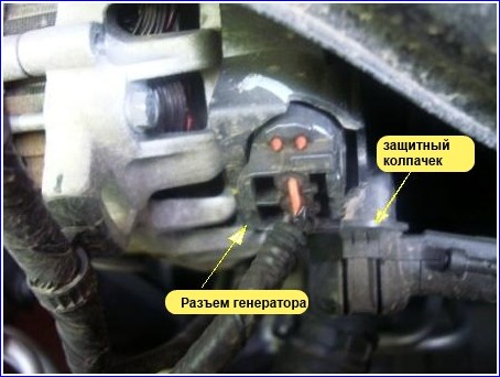
Remove the protective cap from the "B" terminal of the generator.
Remove the nut that secures the wire to the "B" terminal of the generator.
Remove the wire from the "B" terminal of the generator.
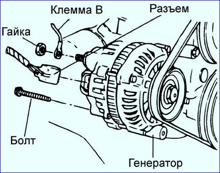
Disconnect the generator connectors
Loosen alternator mounting pivot bolt B and tensioner mounting bolt A.
Loosen the alternator drive belt by turning adjusting bolt C.
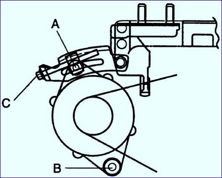
Remove the drive belt from the alternator pulley.
Remove the bolt securing the tensioner.
Remove the generator hinge bolt.
Loosen the adjustment bracket bolt and rotate the bracket.
Remove the alternator from the engine.
Generator disassembly
Install soft protective pads on the vice jaws to prevent damage to the generator parts.
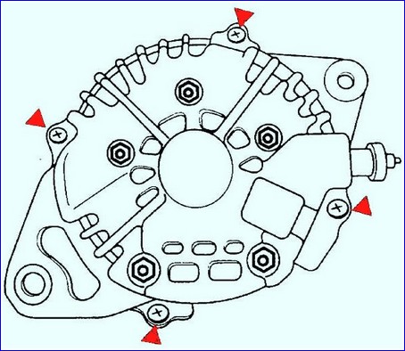
Fix the generator in a vise and remove the four screws securing the rear cover of the generator.
Heat the back cover with a 200 W soldering iron and remove it from the generator.
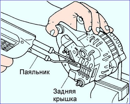
If the back cover is not heated, it is very difficult to remove it due to the very tight fit.
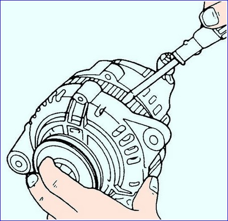
Use a flat-blade screwdriver to remove the front cover of the generator along with the rotor.
Be careful not to lose the retaining spring, which is located near the rear bearing.
Install soft protective pads on the vice jaws to prevent damage to the generator parts.
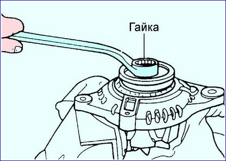
Clamp the rotor in a vise and remove the nut, then remove the pulley, rotor and front cover
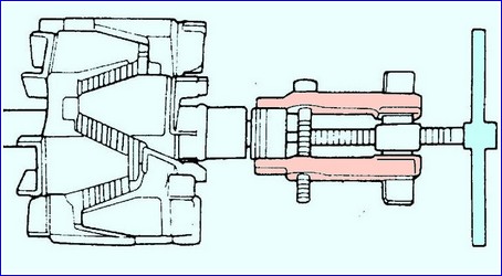
If necessary, use a puller to remove the front bearing from the alternator shaft.
Remove the nut on terminal B and remove the insulating sleeves
Remove the five screws and remove the straightener and brush holder.
Separate the back cover and stator.
Unsolder the rectifier and wires with a soldering iron, then remove the voltage regulator.
Desoldering should be carried out for no more than 5 s, otherwise the voltage regulator may be damaged.
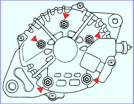
Replace the brushes. Unsolder the braided wire and remove the brush
Checking the generator rotor
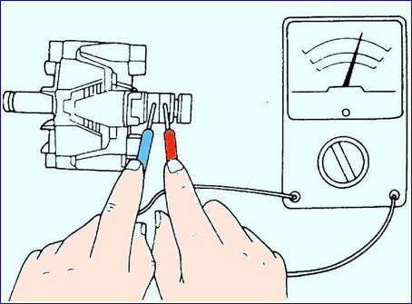
Measure the resistance between slip rings with an ohmmeter.
If the resistance is not as specified, replace the rotor.
Resistance: 3.5-4.5 ohms
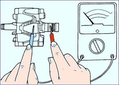
Using an ohmmeter, check the continuity between the slip ring and the rotor armature.
If there is continuity, replace the rotor.
If the surface of the slip ring has roughness or signs of wear, sand it down
Checking the generator stator
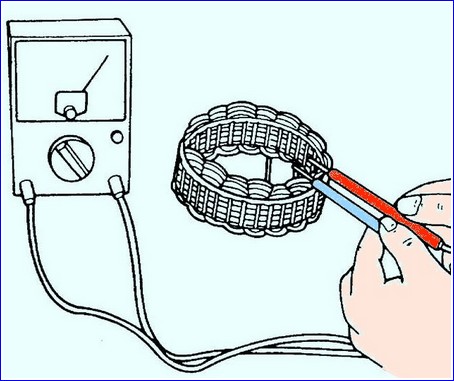
Using an ohmmeter, check the continuity between the wires of the stator coil.
If there is no continuity, replace the stator.
Using an ohmmeter, check the conductivity between the stator coils.
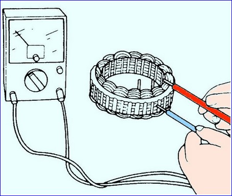
If there is continuity, replace the stator
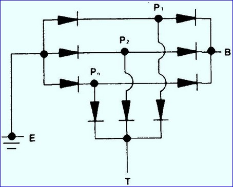
Checking the generator rectifier unit
|
Negative (black) |
Positive (red) |
Conductivity |
|---|---|---|
|
E |
Pn, P1, P2, P3 |
0 |
|
B |
Pn, P1, P2, P3 |
X |
|
T |
Pn, P1, P2, P3 |
X |
|
Pn, P1, P2, P3 |
E |
X |
|
B |
0 |
|
|
Pn, P2, P3 |
T |
0 |
|
Pn |
T |
X |
Use an ohmmeter to check the continuity between the terminals of each diode.
Replace the rectifier unit if necessary.
Checking the generator bearings
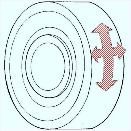
Check the bearing for smooth running, no binding, running noise, and play.
If there are any defects, replace the bearing.
Building a generator
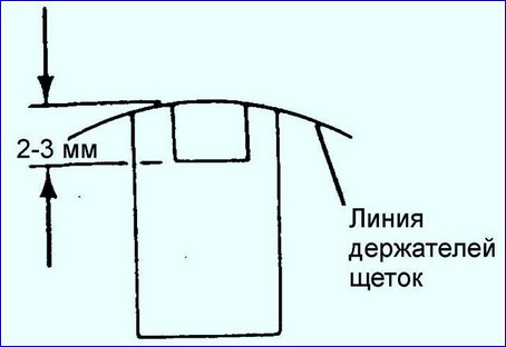
Install the brushes and solder the braided wire so that the wear limit line of the brush protrudes 2-3 mm from the brush holder.
Solder the voltage regulator to the rectifier and stator windings.
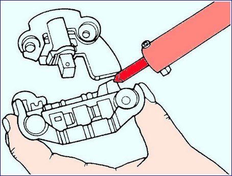
Soldering should be carried out for no more than 5 s, otherwise the voltage regulator may be damaged.
Assemble the back cover andtator.
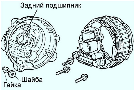
Install the screws that secure the rectifier and brush holder.
Tightening torque: 2.0 - 5.4 Nm
Install the grommets on terminal B and secure them with the nut.
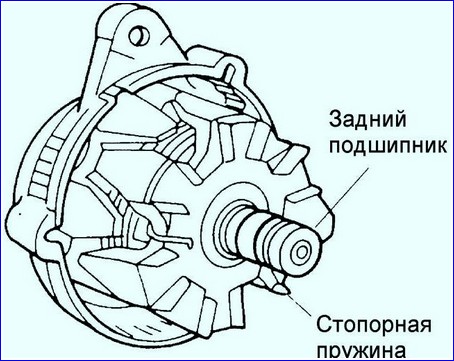
Install the rear bearing and secure with the retaining spring.
Check that the groove in the bearing seat is flush with the face of the bearing.
Install the alternator front bearing.
To install the bearing, it is advisable to use a hand press with a mandrel, the diameter of which corresponds to the diameter of the outer ring of the bearing.
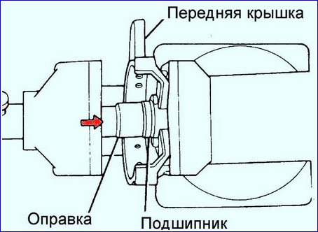
Clamp the rotor in a vise, install the front cover and pulley on it.
Fix the pulley with a nut. Tightening torque: 59–98 Nm
Install the back cover of the generator and secure with four screws. Tightening torque: 2.9 - 6.4 Nm
Generator installation
Mount the generator to the engine.
Insert, but do not tighten, the alternator pivot bolt.
Return the bracket to its original position.
Install the tensioner on the bracket.
Insert, but do not tighten, the tensioner mounting bolt.
Install the alternator drive belt onto the alternator pulley.
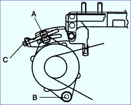
Turn the adjusting bolt "C" to adjust the alternator drive belt tension.
Alternator drive belt deflection:
- - New 5.5-7.0 mm
- - Used 6.0-7.0mm
Tighten the adjusting plate trim bolt.
Tightening torque: 19 - 26 Nm
Tighten the pivot bolt and bracket bolt.
Tightening torque: 38 - 51 Nm
Connect the "L" and "S" connectors to the generator.
Connect the wire to the "B" terminal of the generator.
Use a nut to secure the wire to the "B" terminal.
Cover the "B" terminal of the generator with a protective cap.
Install the air inlet and secure it with a clamp.
Install a fresh air intake.
Install the front fresh air intake bolts.
Connect the cable to the negative battery terminal.
Make sure the battery wires are properly connected.
Do not use high voltage instruments such as a megger to test resistances.
Remember that battery voltage is always applied to the alternator's B terminal.
Do not ground terminal "L" while the engine is running.
Do not start the engine while terminals "L" and "S" are disconnected from the generator.


