Put the car on a two-post lift
Remove the top engine covers
Remove the battery cover.
Disconnect the wires from the battery terminals, starting with the negative terminal.
Remove the engine undertray.
Drain the gearbox oil.
Disconnect wiring harnesses:
- - battery powered;
- - from the battery shelf;
- - from the injection computer.
Remove the battery, ECU and battery tray.
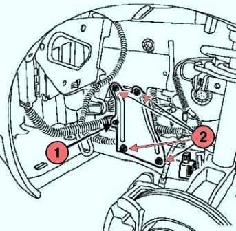
Disconnect the wiring harness from the side amplifier, unscrew the mounting bolts and remove the side amplifier (Fig. 1).
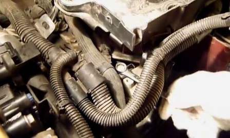
Using a 13 key, we unscrew the bolt securing the clamp holding the automatic transmission cooling hose.
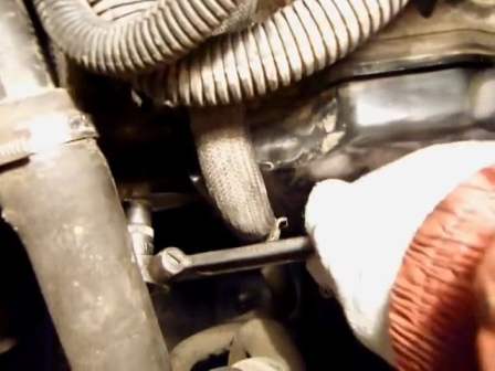
From the bottom with a head of 13, we unscrew the bolt securing the collar of the automatic transmission cooling hose flanging.
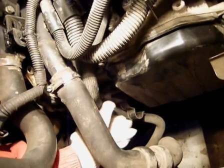
Let's move the automatic transmission cooling hose to the side for access to the hydraulic distributor cover (Fig. 4).
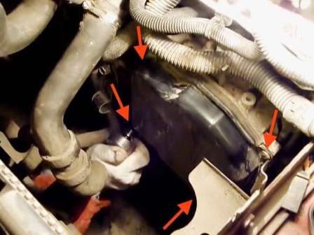
Using the TORX T30 wrench, unscrew the four bolts securing the hydraulic distributor cover (we try not to break the edges of the bolts, you can tap before unscrewing).
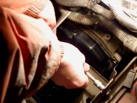
Unscrew the bracket with a 10 head.
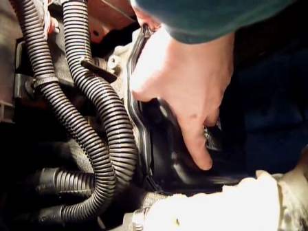
Remove the valve cover (you need to be careful, oil may leak).
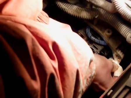
We wipe the contact plane of the automatic transmission crankcase with a rag so that dirt does not get in when removing the valve block.
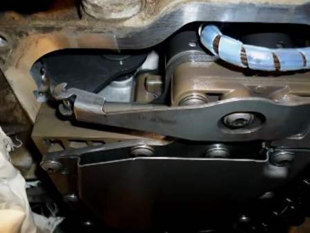
Remembering the position of the toggle elements
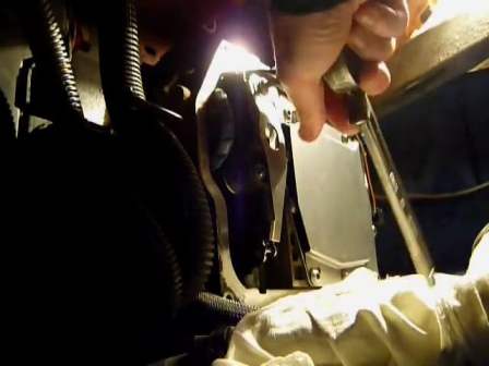
We unscrew the bolt securing the lamellar spring lever (Fig. 10)
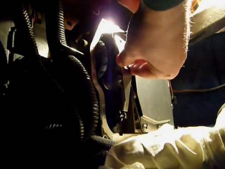
Removing the lamellar spring lever (Fig. 11)
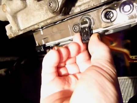
From connect the connectors of the wiring harnesses to the solenoid valves
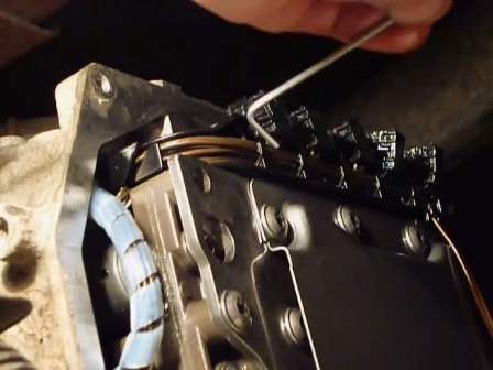
Valve harness connectors are conveniently disconnected using a bent metal bar or a thin hex.
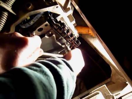
Using the TORX T30 wrench, unscrew the seven bolts securing the valve body.
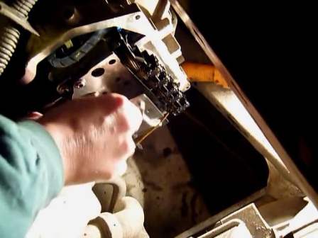
Remove the hydraulic distributor plate
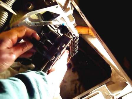
We take the valve body out of the box crankcase, disconnect the two wire harness connectors and remove the automatic transmission hydraulic valve.
Install
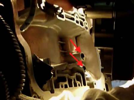
Replace two o-rings (shown by arrows in the figure)
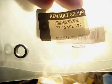
O-ring markings
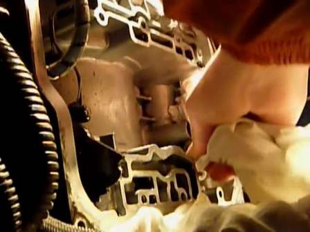
We wipe the inner cavity of the crankcase and mating surface with a non-fluffy cloth
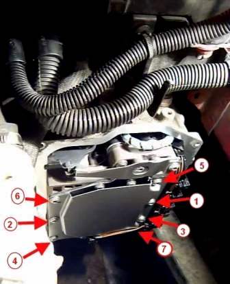
Installing the hydraulic distributor after centering it with bolts 4 and 5 shown in the figure.
We screw in the rest of the bolts.
In the order shown in figure 5, tighten the hydraulic distributor mounting bolts to the required torque (7.5 Nm).


