The principle of operation of the exterior light switch, direction indicators and fog light and wiper switch
Lever switches for exterior lighting, direction indicators and fog lights and windshield wipers form a single non-separable unit, called the "steering column switch block"
This element consists of one control stage, made on diodes and switches.
When certain contacts of the steering column switch block are closed, the UCH recognizes the driver's input.
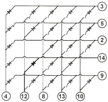
Example: The UCH determines the closure of contacts 12 and 14 as a command to turn on the right turn indicators.
Permanent connections 4-3, 12-5, 8-2, 13-14, 10-9 are used to diagnose the steering column switch box and UCH connection circuits.
Basic faults of the switch block:
- - malfunction in the circuit between the switch box and the UCH;
- - internal electronics failure.
Pin (3) of the black 12-track connector of the switch box is connected to pin (14) of the 40-track PE2 connector of the UCH;
- - contact (4) - with contact (9);
- -(5)-(12);
- -(12)-(15);
- -(2)-(4);
- -(8)-(17);
- -(14)-(11);
- -(13)-(5);
- -(9)-(2);
- -(10)-(19).
These wires must not be damaged and must not short to ground.

Removing paddle shifters
Locking the airbag computer.
When the airbag computer is locked, the electric steering lock is also unlocked.
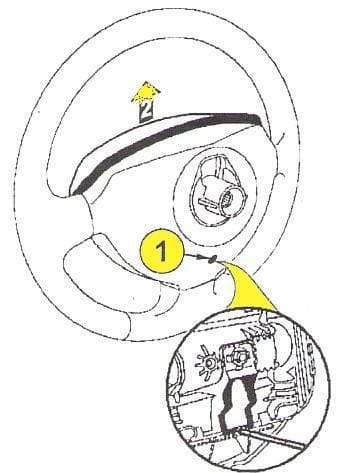
Insert a screwdriver into hole 1 (Fig. 1).
Make an upward movement 2 (fig. 1).
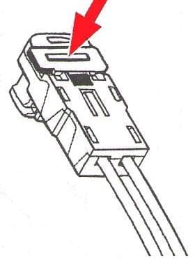
Disconnect the airbag connectors on the steering wheel (along the arrow in Figure 3), using a screwdriver at the point (see the arrow, Figure 2).
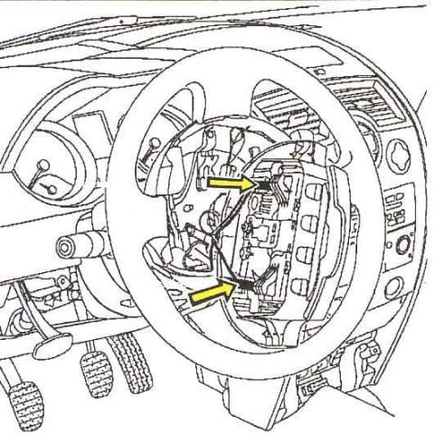
Set the wheels to the straight ahead position.
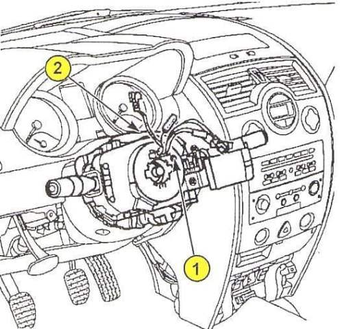
Remove the steering wheel mounting bolt, steering wheel and steering column switch covers.
Before removing the steering column switch block, mark its position, making sure that the “0” mark of the contact disk is against the fixed pointer (see Fig. 4).
Loosen bolt 2 (fig. 4) fastening the contact disk.
Partially release the steering column switch block to disconnect the connectors.
Remove the block of steering column switches.
Installation
Make sure the wheels are in the straight ahead position and that the contact disc mark is in the 0 position.
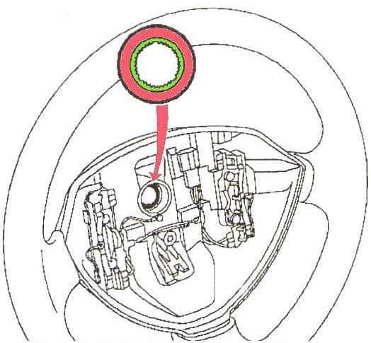
The steering wheel hub must fit freely into the splines with guides (see Fig. 5).
Do not damage the spline guides.
The steering wheel bolt must be replaced after each removal.
The torque of the steering wheel bolt is 44 Nm.


