")
")
")
")
")
")
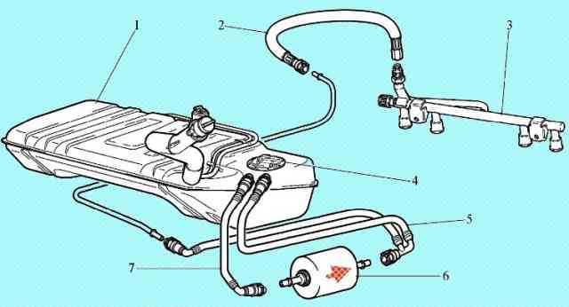
Chevrolet Niva cars with an electronically controlled throttle valve use a fuel supply system with a drainless fuel rail
The function of the fuel supply system is to ensure that the required amount of fuel is supplied to the engine in all operating modes.
Fuel is supplied to the engine by nozzles installed in the intake pipe.
An electric fuel pump installed in the fuel tank supplies fuel through the main fuel filter and fuel supply hoses to the injector rail.
The fuel pressure regulator built into the electric fuel pump maintains the pressure of the fuel supplied to the injectors within 364-400 kPa, depending on the engine operating mode.
The controller turns on the fuel injectors in series. Each of the injectors turns on every 720° of crankshaft rotation.
The controller signal that controls the injector is a pulse, the duration of which corresponds to the amount of fuel required by the engine.
This pulse is given at a certain moment of crankshaft rotation, which depends on the engine operating mode.
A control signal applied to the injector opens the normally closed injector valve, supplying pressurized fuel to the inlet.
The amount of fuel supplied is proportional to the time during which the injectors are open (injection pulse duration).
The controller maintains the optimal air/fuel ratio by changing the pulse duration.
Increasing the duration of the injection pulse leads to an increase in the amount of fuel supplied at a constant air flow (enrichment of the mixture).
Reducing the duration of the injection pulse leads to a decrease in the amount of fuel supplied at a constant air flow (lean mixture).
Electric fuel pump module (MEBN)
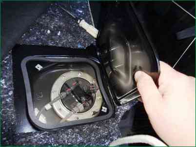
The submersible MEBN is installed in the fuel tank (Fig. 2).
The electric fuel pump module (Fig. 3) includes a turbine-type electric fuel pump, a fuel pressure regulator, a strainer, a coarse fuel filter and a fuel level sensor.
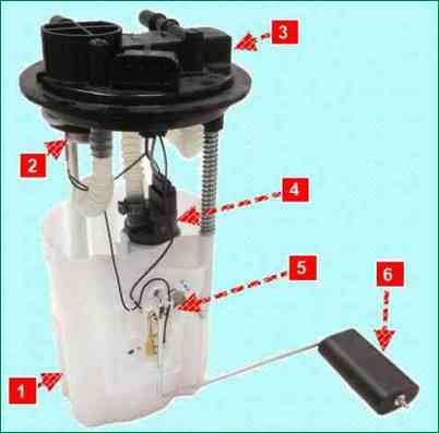
The pump supplies fuel from the fuel tank through the main fuel filter to the injector rail.
The electric fuel pump is turned on by the controller through a relay.
When the ignition is turned on, the controller energizes the relay for 2 seconds to create the necessary fuel pressure in the injector rail.
If the engine does not start cranking within this time, the controller turns off the relay and waits for cranking to begin. After it starts, the controller turns on the relay again.
If the ignition was turned on three times without cranking the engine, then the next switching on of the electric fuel pump relay is possible only with the start of cranking.
WARNING.
Operating a car with an almost empty tank is not allowed, as this can lead to premature wear and failure of the electric fuel pump.
Mesh filter
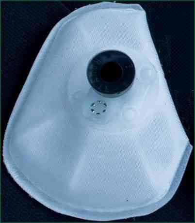
The mesh filter (Fig. 4) is designed to trap particles larger than 60 microns entering the electric fuel pump along with the fuel, which can lead to a malfunction of the injection system.
The filter consists of a plastic frame covered with a polyamide cloth, a lock washer installed in the socket of the plastic housing and a bushing around the fitting.
Fuel filter
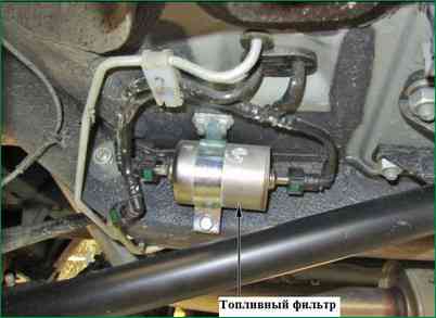
The fuel filter is installed under the underbody near the fuel tank (Fig. 5).
The filter is built into the supply line between the electric fuel pump and the fuel rail.
The filter has a steel body with fittings at both ends. The filter element is made of paper and is designed to trap particles that can lead to malfunction of the injection system.
Injector ramp
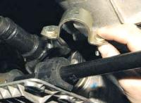
The injector rail is a hollow tube with injectors mounted on it.
The injector rail is fixed with two bolts on the intake pipe (fig. 6).
Fuel under pressure is fed into the internal cavity of the rail, and from there through the nozzles into the intake pipe.
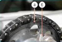
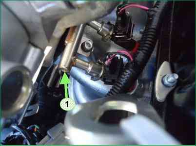
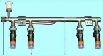
On the injector rail (Fig. 7) there is a fitting 1 for controlling fuel pressure, closed with a screw plug.
A number of diagnostic procedures during vehicle maintenance or troubleshooting require fuel pressure monitoring.
Using a pressure gauge connected to the fitting, you can determine the pressure of the fuel supplied to the injectors.
Fuel injectors
Nozzle 2 (Fig. 7) of the multiport injection system is an electromagnetic device that doses the fuel supply under pressure into the engine intake pipe.
The nozzles are fixed to the ramp with spring clips.
The upper and lower ends of the nozzles are sealed with O-rings, which must always be replaced with new ones when removing and installing the nozzles.
The controller controls the injector solenoid valve, which allows fuel to pass through the guide plate to atomize the fuel.
The guide plate has holes that direct the fuel to form a conical flame.
The fuel jet is aimed at the intake valve. Before the fuel enters the combustion chamber, it evaporates and mixes with air.
An injector that has a stuck valve in a partially open state causes a loss of pressure in the injector rail after the electric fuel pump is turned off, so some engines will experience an increase in cranking time.
In addition, a nozzle with a stuck valve can cause pre-ignition, as some fuel will enter the engine after it is turned off.
Fuel management modes
As mentioned earlier in this chapter, the amount of fuel delivered through the injectors is controlled by the controller.
Fuel is supplied by one of two different methods: synchronous, i.e. in a certain position of the crankshaft, or asynchronous, i.e. without synchronization with the rotation of the crankshaft.
Simultaneous fuel injection is the preferred method.
Synchronization of the operation of the injectors is ensured by using the signals of the crankshaft position sensor and the phase sensor.
The controller calculates the firing moment of each injector, with fuel being injected once per full cycle of the corresponding cylinder.
This method allows you to more accurately dose the fuel into the cylinders and reduce the level of toxicity of exhaust gases.
Asynchronous fuel supply is used in the starting mode and dynamic modes of engine operation.
The controller processes the sensor signals, determines the engine operation mode and calculates the duration of the fuel injection pulse.
To increase the amount of fuel supplied, the duration of the injection pulse is increased, to reduce it, it is shortened.
The duration of the injection pulse can be checked using the diagnostic tool.
Fuel control is carried out in one of several modes described below.
Fuel cut off
Fuel is not supplied in the following cases:
- - ignition off (this prevents glow ignition);
- - engine crankshaft does not rotate (no DPKV signal);
- - if the controller detects the presence of misfires in one or more cylinders, the fuel supply to these cylinders is stopped and the malfunction indicator starts flashing;
- - the engine speed exceeds the limit value of about 6200 rpm (the fuel supply is turned off together with the closing throttle and lowering the UOZ);
- - when "rolling out" in gear and when "re-throwing" on a stationary car, if the engine speed exceeds 2000 rpm, the accelerator pedal is not pressed, the coolant temperature is above 40 ° C.
Start mode
When the ignition is turned on, the controller turns on the electric fuel pump using a relay, which creates fuel pressure in the injector rail.
The controller processes the signal from the coolant temperature sensor to determine the duration of the injection pulses required for starting.
When the engine crankshaft begins to crank during start-up, the controller generates an injector activation pulse, the duration of which depends on the coolant temperature, cranking time and rpm increase.
On a cold engine, the injection pulse increases to increase the amount of fuel, and on a warm engine, the pulse duration decreases.
The system operates in start mode until a certain engine speed (desired idle speed) is reached, the value of which depends on the temperature of the coolant.
WARNING.
A necessary condition for starting the engine is to achieve engine speed when the starter is scrolling to a value of at least 80 rpm, while the voltage in the car's on-board network should not be lower than 6 V.
Open Loop Fuel Control Mode
After starting the engine and before the conditions for entering the closed loop mode are met (the control oxygen sensor is warmed up to the required temperature), the controller controls the fuel supply in open loop mode.
In open loop mode, the controller calculates the duration of the injection pulses without taking into account the presence of oxygen in the exhaust gases.
The calculations are based on a database of crankshaft speed, mass air flow, coolant temperature and the requested torque (this is expressed in the throttle position, UOS and directly in the fuel supply), which can additionally be affected by the inclusion of electrical consumers (light, heating seats, fan, etc.).
Power enrichment mode
The controller monitors the position of the accelerator pedal and the engine speed to determine when maximum engine power is needed.
To develop maximum power, a richer composition of the fuel mixture is required (the UDC control mode is disabled), which is done by increasing the duration of the injection pulses.
Compensation for changes in the voltage of the on-board network
When the voltage of the on-board network decreases, the accumulation of energy in the ignition coils is slower, and the mechanical movement of the injector solenoid valve takes longer.
The controller compensates for the voltage drop of the on-board network by increasing the time of energy accumulation in the ignition coil and the duration of the injection pulses.
Accordingly, with an increase in the voltage in the vehicle's on-board network, the controller reduces the energy accumulation time in the ignition coil and the duration of the injection pulses.
Closed-loop fuel control
The system enters closed loop mode when all of the following conditions are met:
- - 1 - The control oxygen sensor is warm enough for normal operation (the "dew point" has been passed - the temperature on the ceramic of the UDC sensing element exceeds the temperature determined depending on the ambient temperature, the output signal goes beyond the range of 300-600 mV).
- - 2 - The coolant temperature is above a certain value.
- - 3 - The engine has been running for a certain period of time since starting, depending on the temperature of the coolant at the time of starting.
- - 4 - The engine does not operate in any of the following modes: engine start, fuel shutdown, maximum power mode, ECM protection mode.
- - 5 - The engine operates in a certain range according to the load parameter.
In closed loop fuel control mode, the controller initially calculates the injection pulse width using the same sensors as in open loop mode (basic calculation).
The difference is that in closed loop mode, the controller uses the signal from the control oxygen sensor to adjust the injection pulse width calculations in order to maximize the efficiency of the catalytic converter.
There are two types of fuel trim - current trim and self-learning trim.
The first (current) adjustment is calculated from the oxygen sensor readings and can be changed relatively quickly to compensate for current deviations in the composition of the mixture from stoichiometric.
The second (self-learning adjustment) is calculated for each set of RPM-Load parameters based on the current adjustment and changes relatively slowly.
The current adjustment is reset every time the ignition is turned off.
The self-learning correction is permanently stored in the controller memory until the "Reset ECU with initialization" mode is performed using the diagnostic tool.
The purpose of self-learning correction is to compensate for deviations in the composition of the air-fuel mixture from stoichiometric, resulting from a spread in the characteristics of ECM elements, tolerances during engine manufacture, as well as deviations in engine parameters during operation (wear, coking, etc.).
To more accurately compensate for the deviations that occur, the entire range of engine operation is divided into 4 characteristic learning zones:
- - idle;
- - high speed at low load;
- - partial loads;
- - high loads.
When the engine is running in any of the zones, according to a certain logic, the duration of the injection pulses is corrected until the actual composition of the mixture reaches the optimal value.
When changing the engine operating mode, the last value of the correction factor for this zone is stored in the controller's RAM (RAM).
The correction factors obtained in this way characterize a specific engine and are used to calculate the duration of the injection pulse when the system is operating in open loop mode and at start-up, without being able to change.
The correction value at which closed loop fuel control is not required is 1 (it is 0 for the Idle self-learning fuel correction parameter).
Any change from 1(0) indicates that the closed loop fuel control function is changing the injection pulse width.
If the closed loop fuel trim value is greater than 1(0), the injection pulse width increases, i.e. increase in fuel supply.
If the closed loop fuel trim value is less than 1(0), the injection pulse width will decrease, i.e. decrease in fuel supply.
The limit range for changing the current fuel trim and self-learning trim is 1±0.25 (±5).
If any of the correction factors goes beyond the control limits towards enrichment or leanness of the mixture, it indicates a malfunction in the engine or ECM (deviation in fuel pressure, air leakage, leakage in the exhaust system, etc.).
The self-learning correction for fuel control on vehicles with a catalytic converter is a continuous process throughout the life of the vehicle and ensures compliance with stringent emission regulations.
In this ECM, when the battery is disconnected, the values of the adaptation correction factors are not reset.