You will need: micrometer, caliper, ruler.
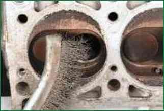
Pre-soak the soot with kerosene. Mechanical cleaning of soot is possible
Be careful not to inhale the dust generated when cleaning the combustion chambers.
To prevent the formation of dust, periodically moisten the soot with kerosene
Remove carbon deposits from combustion chambers
Inspect the head.
If there is a suspicion of cracks in the cylinder head (especially if coolant enters the crankcase or oil into the coolant), check the tightness of the cylinder head on a special stand (in repair shops with the appropriate equipment).
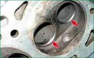
Check the condition of the valve seats.
The seat bevels must be free of wear, pitting, corrosion, etc.
Valve seats can be replaced at a specialist workshop.
Minor damage (minor scratches, scratches, etc.) can be removed by lapping the valves (see "Lapping the valves").
More significant defects in valve seats are eliminated by grinding.
It is recommended that saddles be ground in a specialized workshop, as this requires special tools and equipment.
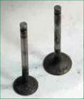
Remove carbon from the valves and inspect them.
Deformation of the valve stem and cracks on its plate are not allowed.
Replace the valve if damaged.
Check if the working bevel is too worn or damaged.
Grinding of the working chamfer of valves is allowed (in repair shops with the appropriate equipment).
After grinding, the angle of the chamfer relative to the plane of the plate should be 45°30’ ±5’, and the thickness of the cylindrical part of the plate should be at least 0.5 mm.
In addition, the exhaust valve must retain the alloy layer applied to the chamfer.
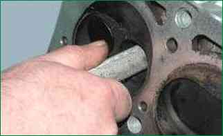
Measure the diameter of the hole in the guide bushings, calculate the clearance between the valve stems and bushings.
The inner diameter of the bushings should be:
- - for inlet valves 8.022 - 8.040 mm;
- - for exhaust valves 8.029 - 8.047 mm.
It is allowed to determine the diameter by gauge (go/no go) as shown.
Mounting clearance for new bushings and valves:
- - for inlet valves 0.022 - 0.055 mm;
- - for exhaust valves 0.029 - 0.062 mm.
Maximum allowable clearance (during wear) - 0.15 mm.
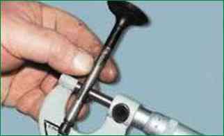
Measure the valve stem diameters. The stem diameter of all valves must be 7.985–8.000 mm
Replace valve stem seals regardless of their condition.
Inspect the valve levers.
On surfaces mating with the valve stem, with the camshaft cam and with the spherical end of the adjusting bolt, scoring and marks are not allowed. Replace levers if damaged.
Inspect the valve springs.
Cracks and loss of spring elasticity are not allowed.
Replace springs if necessary. If possible, determine the elasticity of the springs by their deformation under load.
According to the specifications for the outer spring:
- – free height 50 mm;
- - height under load 283.39 ± 14.7 N (28.9 ± 1.5 kgf) - 33.7 mm;
- - height under load 452.06 ± 22.55 N (46.1 ± 2.3 kgf) - 24 mm.
For internal spring:
- – free height 39.2 mm;
- - height under load 136.30 ± 6.86 N (13.9 ± 0.7 kgf) - 29.7 mm;
- - height under load 275.55 ± 13.73 N (28.1 ± 1.4 kgf) - 20 mm.
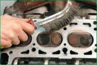
Clean the mating surface of the head from the remnants of the gasket and check the flatness of this surface.
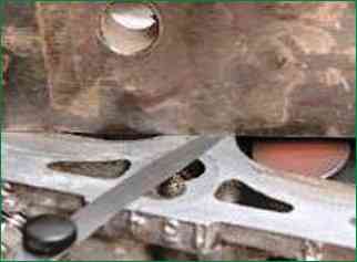
To do this, place a metal ruler with an edge on the surface of the head in the middle along the axis of the head, and then measure the gap between the plane of the head and the ruler along the diagonals and with a feeler gauge.
Replace the head if the gap exceeds 0.1mm.
Always replace the cylinder head gasket with a new one, since a gasket removed from the engine, even outwardly undamaged gasket, may be strongly compressed and will not ensure the tightness of the seal.


