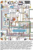
The ignition distributor with a built-in Hall sensor produces voltage pulses, which the switch converts into current pulses in the primary winding of the ignition coil
The grooves of the roller are offset relative to its axis to ensure the correct installation of the sensor-distributor in a certain position.
Removing the distribution sensor
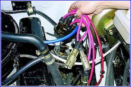
Remove the distributor cap with tips and high-voltage wires.
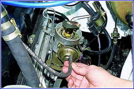
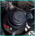
Remove the vacuum regulator hose (Fig. 2).
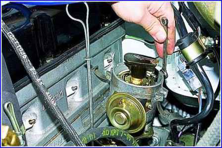
Using the “7” key, we unscrew the low-voltage wire fastening nut
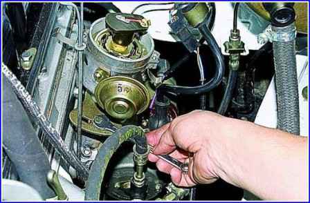
Using the “10” key, we unscrew the octane corrector fastening bolt
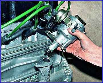
Remove the distributor.
Install the distribution sensor in reverse order.
Remember, however, that the slot in the drive shaft sleeve is offset and the sensor can only be installed in one position.
Removing the distributor assembly with the oil pump drive

Remove the distributor cap with tips and high-voltage wires.
In this position, we remember or mark the position of the slider relative to the body.

Disconnect the switch wire from the distributor

Disconnect the vacuum regulator hose.

Using the “13” key, we unscrew the two fastening nuts
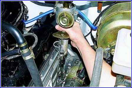
Remove the sensor-distributor assembly with the oil pump drive from the engine.
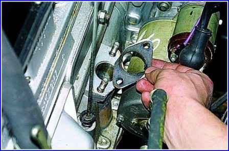
A gasket is installed under the drive.
If the position of the crankshaft remains unchanged, install the distribution sensor (slider opposite the mark) in reverse order
After that, we adjust the ignition timing (see the article - Adjusting the ignition timing of the ZMZ-402 engine).
If the position of the crankshaft has changed, install the distribution sensor in the following sequence:
- move the piston of the first cylinder to TDC, aligning the corresponding pulley mark with the index protrusion on the cylinder block.
At the same time, both valves of the first cylinder are closed (see the article - Adjusting the valve clearances of the ZMZ-402 engine).
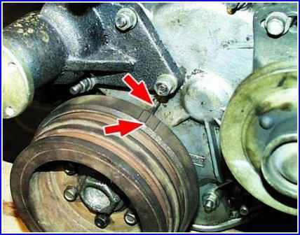
Label on the ZMZ-402 engine (Fig. 8)
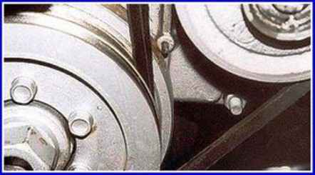
Label on the UMZ-4215 engine (Fig. 9)
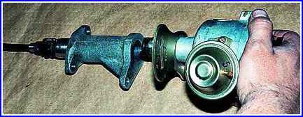
Using the “10” key, we unscrew the octane corrector screw and disconnect the distribution sensor from the drive (Fig. 10).
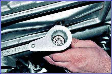
Turning the drive shaft by 45° (the position is shown in Fig. 11), install the drive into the cylinder block.
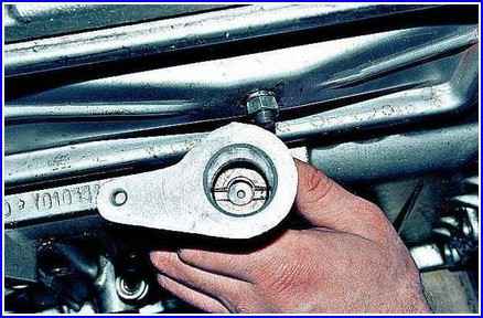
The roller will return to its original position, its slot will become parallel to the longitudinal axis of the engine and will be shifted outward relative to the center of the roller (Fig. 12).
We install the distribution sensor and adjust the ignition (see the article - Adjusting the ignition timing of the ZMZ-402 engine).


