Most of the car's electrical circuits are protected by fuses installed in the mounting block
In the mounting blocks, relays of devices that consume high current are also installed.
The main mounting block is located in the instrument panel on the left side below and is closed with a cover, and the additional mounting block is installed in the engine compartment on its left mudguard.
Before you replace a blown fuse, find out the cause of the blown fuse and fix it.
When troubleshooting, it is recommended to look at the circuits that are protected by this fuse.
Replacing fuses and relays in the mounting block located in the passenger compartment
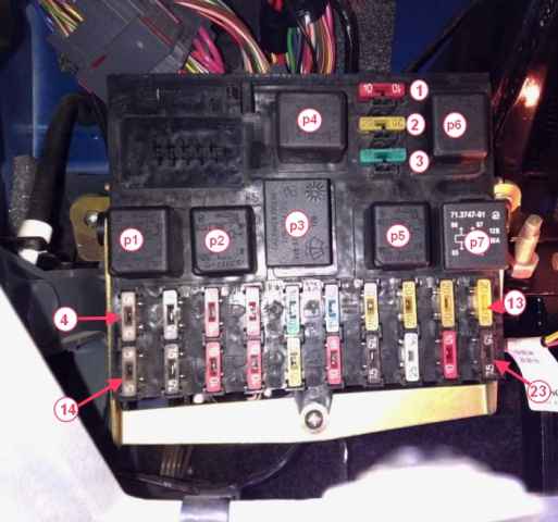
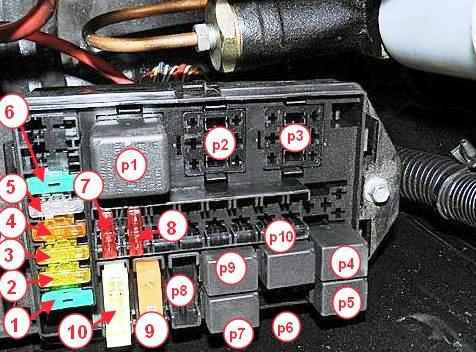
The location of the relays and fuses in the mounting block installed in the passenger compartment is shown in Figure 1, in Table. 1 and 2 show the purpose of relays and fuses.
Use special tweezers to replace the pin fuses.
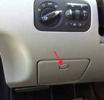
Turn the fixing screw of the mounting block cover (Fig. 2)
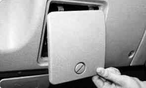
Overcoming the resistance of the upper latches of the cover, remove the cover from the instrument panel (Fig. 3).
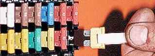
Use special fuse tweezers or manually remove the fuse from the connector (Fig. 4)
Install a fuse of the same rating as the removed one into the connector.
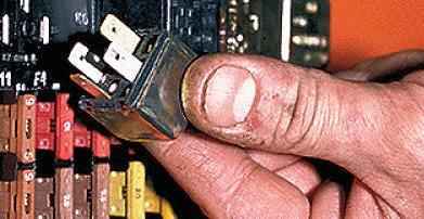
Remove the relay in the same way.
Install the relay of the same type as the removed one
Fuse body color and rating:
Current, A - Fuse body color
- 80 - Beige
- 40 - Orange
- 30 - Green
- 25 - Beige
- 20 - Yellow
- 15 - Blue
- 10 - Red
- 7,5 - Brown
- 5 - Orange
Fuse cases of different ratings are painted in different colors.
In addition, the fuse is marked with the numerical value of the current for which it is designed (nominal value).
Assignment of the relays located in the interior mounting block
Relay number - Name
- P1 - Relay for switching on the dipped headlights
- P2 - Relay for high beam headlights
- P3 - Wiper breaker relay
- Р4 - Relay-interrupter of direction indicators
- P5 - Rear window heating relay
- P6 - Fog lamp relay
- Р7 - Additional (unloading) relay
Before you replace a blown fuse, you need to find out the cause of its blown.
Remove the cause and then install a new fuse.
Fuse-protected circuits
Fuse number - Current strength, A - Protected circuits
- 1 - 10 - Reserve
- 2 - 20 - Same
- 3 - 30 - also
- 4 - 5 - Instrument lamps, port position lights
- 5 - 7.5 - Dipped beam right headlight
- 6 - 10 - High beam right headlight
- 7 - 10 - Right fog light
- 8 - 30 - Power windows, sunroof
- 9 - 15 - Socket for portable lamp
- 10 - 20 - Horn, electric side mirrors
- 11 – 20 - Rear window defroster
- 12 – 20 - Windscreen cleaners and washers
- 13 - 20 - Reserve
- 14 - 5 - Starboard marker lights and license plate lights
- 15 - 7.5 - Left low beam
- 16 - 10 - Left headlight high beam, headlight high beam indicator
- 17 - 10 - Left fog lamp
- 18 – 20 - Electric door lock system
- 19 – 10 - Direction indicators and hazard warning lights
- 20 - 7.5 - Dome lights, engine compartment light with top signals
- 21 - 25 - Heater, cigarette lighter
- 22 - 10 - Instrument cluster, reversing light switch
- 23 - 7.5 - Rear fog lights
Replacing fuses and relays in the auxiliary unit
Open the hood.
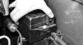
Press out the lock of the cover of the mounting block, located in its front part ...
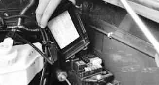
Remove the mounting block cover
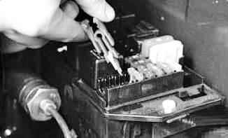
Using fuse tweezers or manually remove the fuse from the connector.
Install a fuse of the same rating as the removed one into the connector.
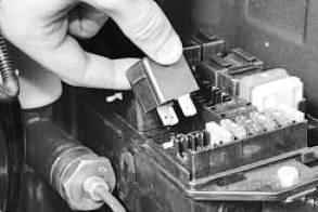
Remove the relay in the same way.
Install the relay of the same type as the removed one
Fuse-protected circuits
Fuse number (current, A) - Protected circuits
- 1 - (30) - fan relay power circuit;
- 2 - (20) - starter relay power circuit;
- 3 - (20) - power circuit of the fuel pump relay;
- 4 - (5) - appliances;
- 5 - (25) - ABS;
- 6 - (30) - fan relay power circuit;
- 7 - (10) - power circuit of the main relay of the engine control system;
- 8 - (10) - ABS;
- 9 - (40) - too;
- 10 - (80-90) - mounting block power supply
Location may vary depending on vehicle equipment
Assignment of the relays located in the mounting block of the engine compartment
Relay - name
- P1 - Starter relay
- P2 - Tailgate washer time switch
- P3 - Place for the relay of the recirculation damper control unit
- P4 - Electric fan relay
- Р5 - Also
- P6 - Compressor relay*
- P7 - Electric fuel pump relay
- P8 - Relay for turning on sound signals
- P9 - Engine control relay
- P10 - A/C relay*
*installed on some cars, depending on the configuration


