How to replace the hydraulic valve compensators of the K4M engine
You will need: the same tools as for replacing the valve stem seals, with the exception of those that are needed directly to replace them (tools are used only for preparatory operations)
And also three additional containers for flushing diesel fuel with a capacity of approximately 2 liters each, a piece of hardened wire with a diameter of 0.5 mm and a length of approximately 10 cm.
We prepare the car for work.
We install it on a lift or inspection ditch.
We remove the timing belt (see the article replacing the timing belt).
Remove the oil separator of the ventilation system.

With a 10 head, unscrew the bolt that secures the probe guide tube bracket to the air intake bracket

Remove the tube with the probe from the socket of the engine pan.
The tube is sealed with a rubber ring.

With a head of 8, we unscrew the two bolts securing the eye

Remove the eye with the bracket

With a head of 8, we unscrew the twenty-four bolts securing the cylinder head cover

With a screwdriver, pry off the cylinder head cover (for the tides on the cover, placing a rag)

Remove the cylinder head cover

We remove two rubber-metal plugs from the cylinder head

Remove the exhaust valve shaft
Removing the intake valve shaft

To check the hydraulic bearings, remove the lever

Remove the hydraulic compensator from the socket of the cylinder head
Checking hydraulic lifters is discussed below.
To remove the pulley, lay the camshaft.

We put an 18 spanner on the pulley fastening nut. We insert a screwdriver through the hole in the pulley.
Leaning on the pulley hub with a screwdriver blade, press the key with the screwdriver rod and turn it counterclockwise.
The pulley should not rotate, and the nut will turn away.

Remove the pulley from the toe of the camshaft

Remove the seal. We also remove the oil seal from the other camshaft

Apply sealant to the mating surface of the cover
We install the cylinder head cover and tighten the bolts of its fastening to the prescribed torque in the sequence indicated in the table.

Having installed the cylinder head cover, with a tool head or a piece of pipe of a suitable size, we press the new camshaft oil seals into the cylinder head sockets, having previously applied a thin layer of engine oil to the working edges of the oil seals.
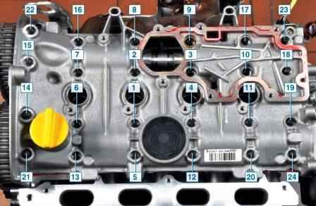
Numbering of cylinder head cover bolts
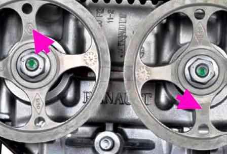
After checking the phases of the gas distribution mechanism and fixing the shafts, we install the toothed pulleys on the toes of the camshafts so that the Renault emblems printed on the spokes of the pulleys are located vertically up (exhaust valve shaft) and down (inlet valve shaft).
Having screwed on the pulley fastening nuts, we slightly tighten them.
We install on the pulleys and pull the timing belt.
Tighten the nuts securing the camshaft pulleys with a tightening torque of 30 Nm and tighten by 84˚.
We turn the crankshaft clockwise two turns and check the correct installation of the valve timing. If necessary, repeat the installation of the valve timing.
Checking and flushing hydraulic valve compensators
The hydraulic gap compensators in the valve drive mechanism are used to compensate for thermal expansion of the drive elements.
The operation of the hydraulic compensator is based on the principle of incompressibility of engine oil, which constantly fills the internal cavity of the hydraulic compensator during engine operation and moves its plunger when a gap appears in the valve drive, ensuring constant contact of the valve drive pressure lever roller with the camshaft cam without clearance. This eliminates the need for valve adjustment during maintenance.
Hydraulic lifters are non-separable compact devices inserted into the sockets of the cylinder head.
Valve knocking of a running engine can be caused by:
- - air ingress into the over-plunger cavities of hydraulic compensators when the oil level in the crankcase is too low or too high, as well as when the car is parked on a slope for a long time;
- - contamination of the precision surfaces of the hydraulic clearance compensators in the valve drive mechanism with sludge from low-quality engine oil (or if it is not replaced in time, as well as if the oil filter is damaged);
- - wear of hydraulic compensators.
If pumping or flushing fails to restore the hydraulic compensators, replace them, as their design is non-separable.
Initially, make sure that extraneous noise during engine operation is caused by a malfunction of the hydraulic lifters:
- - start the engine. In the event of a malfunction of the hydraulic compensators, extraneous noise in the area of the head cover appears immediately after the engine is started and changes in accordance with the change in the engine speed.
If the noise does not appear immediately after starting the engine or does not change when the crankshaft speed changes, the malfunction is not caused by a malfunction of the hydraulic lifters. Moreover, if the noise does not change when changing the speed of the crankshaft, it is likely that the cause of the post horn noise not in the engine;
- - when the engine is idling, make sure that the noise level does not change when the load changes (for example, when switching the automatic transmission selector from position N to position D when disengaging the clutch of a car with a manual transmission or when turning on electrical consumers and air conditioning) .
If the noise level changes, the cause may be a collision of parts due to wear of the connecting rod and main bearings of the crankshaft, and not a malfunction of the hydraulic lifters;
- - warm up the engine to operating temperature. If the noise has decreased or disappeared, it is possible that the rattling of the hydraulic lifters is caused by oil contamination. In this case, it is necessary to flush the hydraulic lifters:
- - if the noise does not disappear, air has probably got into the hydraulic lifters, and it should be removed.
If the oil level in the crankcase is too low, the oil pump will entrain air along with the oil; if the oil level in the crankcase is too high, the oil is agitated and foamed by the counterweights of the crankshaft.
When the car is parked on a slope for a long time, oil flows out of the cavities of the hydraulic compensators and oil channels, and the supply of oil to the hydraulic compensators after starting the engine takes some time, during which the cavity of the hydraulic compensator has time to get air.
In all these cases, when oil with air enters the over-plunger cavity of the hydraulic compensator, the air inside the cavity when the valve is opened will be compressed and the hydraulic compensator will not be compressed, which will lead to a characteristic knock of the valve mechanism with increased clearances.
To bleed air from the hydraulic lifters, do the following:
Check the oil level in the crankcase and top up if necessary;
- - start the engine and warm it up at idle for 1 - 3 minutes;
- - increase the crankshaft speed to 3000 min-1, then sharply reduce to idle speed and let the engine idle;
- - repeat the cycle and check if the noise of the valve drive mechanism has disappeared
If the hydraulic lifters are in good condition, the noise disappears after 10 - 30 cycles;
- - after the noise disappears, repeat to remove air five more times;
- - let the engine idle for 1-3 minutes and make sure that the noise of the valve drive mechanism has disappeared.
If the noise of the valve drive mechanism does not disappear after bleeding and warming up the engine to operating temperature, identify faulty hydraulic lifters as follows.
- 1. Stop the engine and immediately after stopping, set the piston of the 1st cylinder to the TDC position of the compression stroke, remove the cylinder head cover.
- 2. Remove the camshafts.
- 3. to check the operation of the engine hydraulic compensators, press the arm of the rocker arm resting on the hydraulic compensator. If the rocker arm can be moved with little or no effort, the hydraulic lifter is faulty.
- 4. Similarly, check the condition of the hydraulic compensators of the remaining cylinders (the order of operation of cylinders 1-3-4-2).
After identifying faulty hydraulic lifters, you should first try to flush them as follows.
- 1. Remove the rocker arms.
- 2. Remove the defective hydraulic compensator from the cylinder head socket.
- 3. Prepare three identical containers with a capacity of approximately 2 liters for flushing hydraulic lifters.
The dimensions of each container must be sufficient so that the hydraulic compensator, lowered to the bottom of the container in a vertical position, is completely immersed in the liquid.
Fill the containers with clean diesel fuel.
- 4. Place the hydraulic lifter in the first container and clean the outer surface.
- 5. Having immersed the hydraulic compensator in the first container halfway, with the plunger down, lightly pressing the wire through the hole, squeeze the valve ball and, holding the ball depressed, move the hydraulic compensator plunger 5-10 times until the plunger moves completely free.
If the plunger does not move easily, replace the hydraulic compensator.
- 6. Remove the hydraulic compensator from the container and, pressing the valve ball, move the plunger until the diesel fuel flows out of the hydraulic compensator.
- 7. Place the hydraulic lifter in the second container and repeat step 5.
- 8. Remove the hydraulic compensator from the container and drain the diesel fuel from it as described in step 6.
- 9. Place the hydraulic compensator on the bottom of the third container vertically, with the plunger up and wring out the ball of its valve with a wire.
- 10. While holding the valve ball depressed, move the plunger down and then slowly move it up so that the over-plunger cavity of the hydraulic compensator is filled with diesel fuel.
- 11. Remove the hydraulic compensator from the container; holding it with the plunger up, with a little effort, press on the plunger and make sure it stays still.
At the same time, check the overall height of the hydraulic lifter by comparing it with the new hydraulic lifter.
If during the check it was possible to move the hydraulic compensator plunger, repeat steps 9 and 10 until the hydraulic compensator cavity is completely filled with diesel fuel.
If the hydraulic lifter still does not reach working condition after this, or if its overall height is less than the height of the new hydraulic lifter, replace it.
Before assembling the valve drive mechanism, store filled hydraulic lifters only in the vertical position with the plungers up. Avoid getting dirt into the hydraulic lifters.
Install hydraulic lifters on the engine as soon as possible after refueling to avoid possible loss of diesel fuel.
- 12. Install the hydraulic lifters and all removed parts in the reverse order of removal.
- 13. Start the engine and let it idle for 1-3 minutes. If necessary, bleed the hydraulic lifters as described above.
")
")
")
")
")
")