The following types of automatic transmissions are used on the Camry: 1AZ, 2AZ-FE - U241E; 1MZ-FE-U140E
These automatic four-speed transmissions are compact and high-performance and are electronically controlled by ECT (Electronic Controlled Transmission).
The basic construction and operation of these boxes are the same.
The gear ratio, as well as the number of discs and springs, differ depending on the engine model.
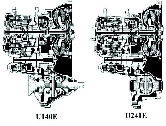
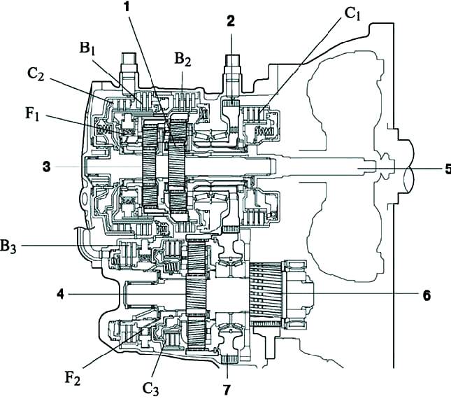
The order of gear shifting is carried out using the electronic control unit
The ECU receives information about the state of the engine, driving conditions, and selects the moment of gear shifting according to road conditions, taking into account the characteristics of the driver
The result is improved fuel economy and improved transmission performance
Automatic transmission control cable drive
The automatic transmission control selector link is installed in the same place in the floor tunnel as the manual transmission control lever
The differential of an automatic transmission is the same as on a manual transmission
Planetary gearbox
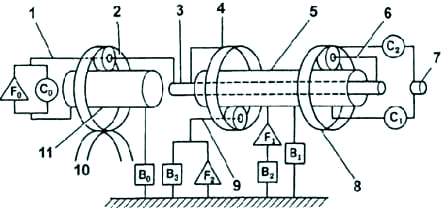
Planetary gearbox: 1 - carrier of the increasing planetary gear set; 2 - the epicycle of the increasing planetary series; 3 - intermediate shaft; 4 - epicycle of the rear planetary gear; 5 - sun gears of the front and rear planetary gear sets
The planetary gearbox contains three planetary gear sets, three lock-up clutches, four brakes and three freewheels.
The power from the engine through the torque converter is transmitted to the input shaft of the planetary gearbox.
Gear shifting is performed by engaging a combination of two controls, which changes the speed of the output shaft.
Elements of the planetary gearbox
Increasing planetary gear set (Co) - connects the carrier and sun wheel of the incremental gear set.
Up row brake (Bo) - stops the up row sun wheel.
Overdrive Clutch #1 (F1) - When the 2nd gear brake is engaged, it prevents counterclockwise rotation of the front and rear planetary sun gears.
Forward clutch (C1) - connects the input shaft and the epicycle of the front planetary gear set.
Second gear brake (B2) - Stops the #1 freewheel outer race, thus inhibiting counterclockwise rotation of the front and rear sun gears.
1st gear and reverse brake (B3) - stops the rear planet carrier.
Freewheel No. 2 (F2) - prohibits counterclockwise rotation of the rear planetary carrier.
Direct clutch (C2) - connects the input shaft and the sun gears of the front and rear planetary gear sets.
Brake for engine braking in second gear (B1) - stops the rotation of the sun gears of the front and rear planetary gear sets.
Overdrive Freewheel (Fo) - Connects the overdrive sun gear and the overdrive carrier when starting the engine.
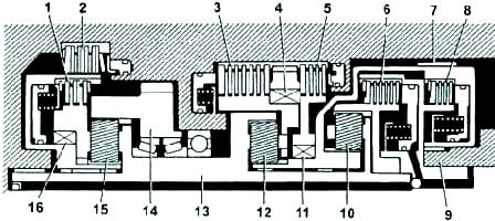
Planetary mechanism: 1 - blocking clutch of the increasing planetary gear set (Co); 2 - brake of the increasing planetary gear set (In); 3 - brake of the first gear and reverse gear (VZ); 4 - freewheel No. 2 (F2); 5 - second gear brake
Hydraulic control system
The control system includes: a pump, a valve block, solenoid valves, hydraulic accumulators, blocking clutches and brakes.
Basic pressure in the system is created by a pump, it is regulated by the control system depending on the load and speed of the vehicle, and ensures the operation of the torque converter, lockup clutches and brakes.
Shift valves control fluid flow to the torque converter and planetary gearbox.
The valve block has three solenoid valves that control gear shifting and torque converter lockup.
Checking the automatic transmission fluid
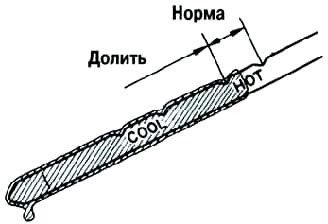
Drive the vehicle to allow the engine and transmission to warm up to normal operating temperature.
Liquid temperature: 70–80 °C.
Stop the vehicle on level ground and apply the parking brake.
With the engine idling and the brake pedal depressed, move the shift lever alternately to all positions "P" to "L" and return to position "P".
Remove the dipstick and clean it. Insert the probe completely into the tube.
Remove the dipstick and check that the liquid level corresponds to the HOT position (fig. 5).
If there are leaks, repair or replace O-rings, seals, plugs or other parts.
Checking and adjusting the throttle control cable
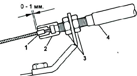
Depress the accelerator pedal fully and make sure the throttle is fully open.
With the accelerator pedal fully released, loosen the adjusting nuts.
Adjust the cable so that the distance between the boot and the stopper on the cable is within the nominal range.
Nominal full throttle distance is 0-1mm.
Tighten the adjusting nuts and recheck.


