Compensation for pedal position sensor failures
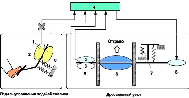
The pedal position sensor includes two (main and secondary) sensor circuits
If there is a malfunction in any of the sensor circuits, the engine electronic control unit detects a difference in signal voltages in these two circuits and switches to emergency operation.
In this mode, the remaining circuit is used to calculate the throttle angle to drive the vehicle in emergency mode.
If both systems are malfunctioning, the engine ECM detects an incorrect signal voltage between the sensor circuits and assumes that the throttle pedal angle corresponds to a fully depressed pedal, and then continues to control the accelerator.
At this time, the vehicle can move in idle mode.

Throttle position sensor failure compensation
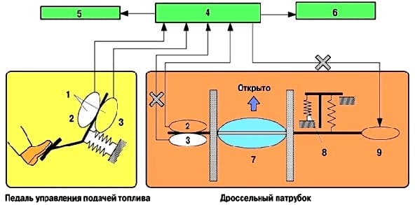
The throttle position sensor includes two (main secondary) sensor circuits.
If there is a malfunction in any of the sensor circuits, the engine electronic control unit detects a difference in signal voltages in these two circuits, turns off the current to the throttle actuator motor and switches to emergency operation.
Then, under the action of the force of the return spring, the throttle valve returns to the set position and remains in this position.
In this case, the vehicle can drive in emergency mode, and the engine power is controlled by controlling the fuel injection and setting the ignition timing according to the opening angle of the accelerator.
A similar control algorithm is used if the engine ECM detects a malfunction in the throttle motor system.

Diagnosis of the engine management system
At the moment a system malfunction is detected, the engine's electronic control unit diagnoses and stores the error.
In addition, the check engine warning light in the instrument cluster comes on or flashes to inform the driver.
The engine ECM will also store fault diagnostic codes (DTCs).
Diagnostic codes can be accessed using a portable tester.
For service technicians.
The time required to clear the control unit of diagnostic codes (DTC) by disconnecting the battery has been increased from 10 seconds (on previous models) to 1 minute.


