Checking the main switch
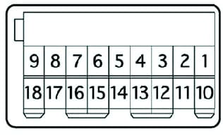
Check for continuity between the main power window switch terminals

If there is no continuity, replace the main switch.
Glass closed
|
Position switch |
Front Passenger Outlet# |
Right Back Pin # |
Left Back Pin# |
|---|---|---|---|
|
UP |
6-131-15 |
6-181-16 |
6-121-10 |
|
OFF |
1-131-15 |
1-181-16 |
6-121-10 |
|
DOWN |
6-151-13 |
6-161-18 |
6-101-12 |
Glass open
|
Position switch |
Front Passenger Outlet# |
Right Back Pin # |
Left Back Pin# |
|---|---|---|---|
|
UP |
6-13 |
6-18 |
6-12 |
|
OFF |
13-15 |
16-18 |
10-12 |
|
DOWN |
6-15 |
6-16 |
6-10 |
Checking the power window motors
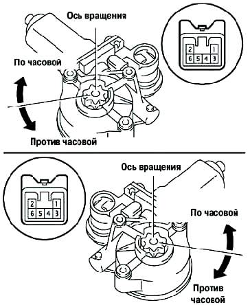
Check the operation of the right front window motor.
Connect terminal 5 of the motor connector to the positive battery terminal and terminal 4 to the negative terminal.
Make sure the motor rotates clockwise.
Reverse the polarity of the connection and make sure the motor rotates counterclockwise.
If at least one test does not match the description, replace the motor.

Check the operation of the power window motors of the remaining doors, setting the same polarity as in the first test.
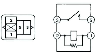
Checking the main power relay
Check for continuity between relay outputs when energized.

If the results do not match those given in the table, replace the relay.
Standard check
|
Pin# |
Status |
Result |
|---|---|---|
|
1-2 |
Permanent |
Handled |
|
3-5 |
Permanent |
Not Conducted |
|
3-5 |
Power Supply between clamps 1 and 2 |
wired |


