You will need: key "10", heads "15", "17", "19"
Remove the oil pan and its gasket
Remove the oil pump.
Remove the camshaft drive chains.

Remove six bolts 1 (Fig. 1), fastening the flywheel, remove the washer 2 of the flywheel bolts and remove the flywheel 3.

Remove six bolts 1 (Fig. 2) and remove the stuffing box holder 2 with the crankshaft rear oil seal 3 pressed into it.
Remove the stuffing box gasket.

If you do not need to remove the pistons from the cylinders, you can not remove the block head, just unscrew the nuts of 3 connecting rod bolts, remove the covers of 5 (Fig. 3) connecting rods and carefully slide the pistons into the cylinders.
Remove the bolts 1 and remove the caps 6 of the main bearings.
If the lids are tight, knock them off with gentle hammer blows.
Remove the upper half rings 4 of the thrust bearing.
Remove crankshaft 2 complete with gear and bushing 7.
Main bearing caps are processed together with the cylinder block, so they are not interchangeable and it is forbidden to depersonalize them when removed.
Remove the shells and the lower half rings of the thrust bearing from the beds of the main bearings and caps.
If you don't intend to change the earbuds, mark them so they can be reinstalled.
Rinse all parts with gasoline and dry.
Inspect the crankshaft. If it has cracks or signs of overheating, replace the shaft.

Remove the plugs (Fig. 4), wash with gasoline and blow out the oil channels of the crankshaft with compressed air.
Put on the plugs and tighten them to a torque of 38–42 Nm (3.8–4.2 kgf m).
If slight scuffing is found on the main and connecting rod journals or the ovality of the journals exceeds 0.01 mm, the journals should be ground to the repair size.
After sanding, polish the necks. It is necessary to grind the shaft journals to one of the repair sizes indicated in the table.
Blur the sharp edges of the chamfers of the oil channels with an abrasive cone.
After grinding, rinse the crankshaft, blow out the oil channels with compressed air, install the main and connecting rod bearing shells of the appropriate repair size.
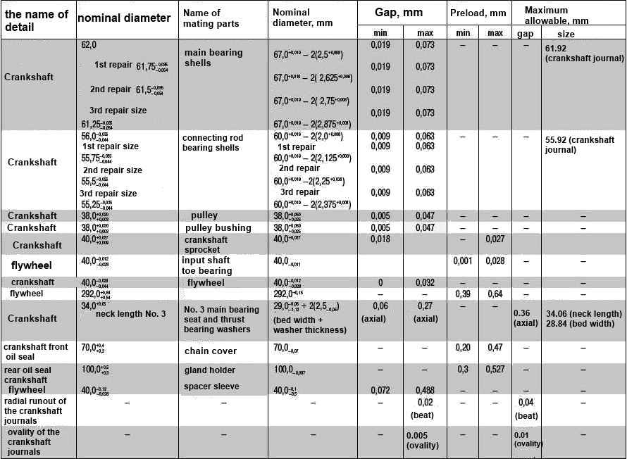
Nominal and maximum allowable dimensions and fit of mating parts of the crankshaft of the ZMZ-409.10 engine
Inspect the main bearing shells. If they have scuffs, peeling or other defects, replace the liners.
Inspect the flywheel.
If the teeth of the flywheel crown are damaged, there are scuffs and other defects on the surface adjacent to the clutch disc, replace the flywheel.
Replace cracked flywheel as well.

A closed-type bearing is pressed into the flywheel, which acts as a support for the toe of the gearbox input shaft.
Inspect the bearing, if defects are found (large play, seizing, etc.), replace the bearing.

Press the bearing out of the flywheel
Press the new bearing flush with the bottom edge of the chamfer of the hole in the flywheel.

Inspect the front and rear crankshaft oil seals in the front cylinder head cover and oil seal holder. They should not be damaged (tears, wear of the working edge, etc.).
Replace damaged oil seals by removing the old oil seal with a screwdriver and pressing in a new one. Moreover, the old oil seal can be used as a mandrel.
When the vehicle has a high mileage, it is recommended to replace both oil seals when disassembling the engine, regardless of their condition.
Measure the diameters of the main and connecting rod journals of the crankshaft.
If the diameters of the connecting rod journals are less than 55.92 mm, the main ones are less than 61.92 mm, grind the journals to the repair size.
All main or connecting rod journals must be ground, even if only one journal is smaller than the specified maximum allowable size.
Check the clearances between the main bearing shells and the crankshaft journals.
The gap should be between 0.019-0.073 mm.

Clearances can be calculated by measuring the diameters of the crankshaft journals and the bores in the main bearings with the liners installed, or using a calibrated plastic wire.

The principle of measuring the gap is to flatten a special plastic calibration wire and measure the width of the resulting print.
To measure the gap between the shaft neck and the liners, a piece of calibrated wire is used, the length of which is 2 mm shorter than the width of the liner
The gauge is located axially on the shaft neck
Measure the gaps in the following order:
- - clean the crankshaft journals and bearing shells from oil deposits;
- - lay the crankshaft in the bed of the main bearings with the liners installed;

- put on the necks of the crankshaft trimmed calibrated plastic wire;

- - install the main bearing caps with liners,

- Install the cover bolts and tighten to 100 Nm (10.0 kgf m).
Do not rotate the crankshaft while doing this;

- - remove the main bearing caps and determine the gap by the flattening of the wire according to the scale printed on the wire package.

Imprint remains on shaft journal "A" or bearing "B"
Install the crankshaft in the reverse order of removal, taking into account the following:
- - liners without grooves are installed in the main bearing caps, and with grooves in the bed;
- - the upper half rings of the thrust bearing are installed in the grooves of the bed of the main bearing No. 3 with an antifriction layer to the crankshaft cheek, the lower ones - together with the cover, and the antennae of the half rings must enter the grooves of the cover;
- - before installation, lubricate the main and connecting rod journals of the crankshaft, the main bearing shells and the thrust bearing half rings with clean engine oil;
- - tighten the bolts of the main bearing caps to a torque of 100–110 Nm (10.0-11.0 kgf m);
- - tighten the flywheel mounting bolts to a torque of 72–80 Nm (7.2–8.0 kgf m);
- - Rotate the crankshaft before attaching the connecting rods. It should rotate easily, without jamming.
")
")
")
")
")
")