Installation of injection pump, injectors, high and low pressure pipes D-245
The mounting plate of the injection pump must be clean; nicks and other damage to the slab are not allowed
The fuel pump gasket must not show visible damage.
When installing the fuel pump, match the marks of the gear wheel of the fuel pump drive and the splined flange.
The spline flange of the fuel pump gear must freely, without jamming, be on the splines of the fuel pump shaft bushing.
The bolts of the fuel pump gear flange must be tightened to a torque of 18-25 Nm.
When installing the fuel pump, be sure to check the fuel injection advance angle.
This is done in the following sequence:
- set the regulator control lever to the position corresponding to the maximum fuel supply.
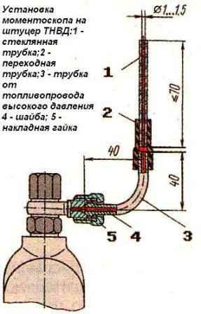
Disconnect the high-pressure tube from the fitting of the first section and connect the momentoscope instead (Fig. 1).
Turn the diesel crankshaft with a wrench clockwise until a fuel momentoscope without air bubbles appears from the glass tube.
- remove some of the fuel from the glass tube by shaking it.
Turn the crankshaft counterclockwise by 30.. .40°.
Slowly rotating the diesel crankshaft clockwise, monitor the fuel level in the tube, at the moment the fuel starts to rise, stop the rotation of the crankshaft.
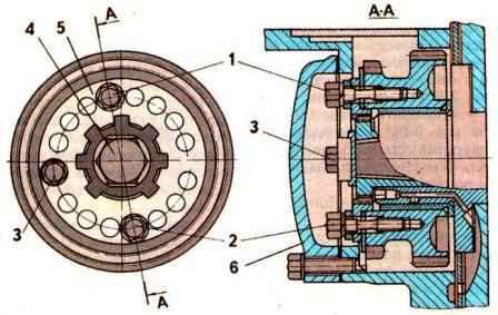
If the latch does not match the hole in the flywheel (Fig. 2), adjust, for which do the following:
- - remove the hatch cover;
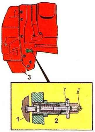
- - unscrew bolts 1, 2 and 3 (Fig. 3) and loosen bolt 3 by ½-1 turn (do not turn the bolt out);
- - align the latch rod 2 (see Fig. 2) with the hole in the flywheel, turning the diesel crankshaft in one direction or another; using a wrench, turn the fuel pump shaft and the splined flange by the nut until the fuel begins to rise in the glass tube 1 (see Fig. 1) of the momentoscope;
- - install bolts 1,2 and 3 (see Fig. 3) in matching holes, trying to arrange them as evenly as possible around the circumference;
- - tighten bolt 3 first, then bolts 1 and 2;
- - put the high pressure tube back in place and remove the retainer rod from the hole in the flywheel;
- - reinstall the manhole cover.
Combination of the splines of the fuel pump bushing and the splined flange when installed on a diesel engine is ensured by turning the crankshaft of the diesel engine or the camshaft of the pump.
Injectors of the same group must be installed on a diesel engine.
Sealing gaskets on the side adjacent to the injectors should be lubricated with grease US-1 GOST 33-51.
The injector mounting bolts must be tightened to a torque of 20-25 Nm.
High pressure pipes must be fixed at a distance of 10-15 mm from the union nuts with clamps with gaskets.
Pipes of low fuel pressure should be blown out with compressed air before installation on a diesel engine.
")
")
")
")
")
")