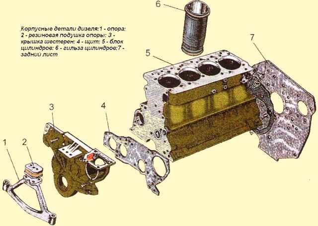
The cylinder block is the main body part of a diesel engine and is a hard cast iron
Four removable sleeves made of special cast iron are installed in the vertical bores of the block
The sleeve is installed in the cylinder block along two centering belts: upper and lower.
In the upper belt, the sleeve is fixed with a shoulder, in the lower belt it is sealed with two rubber rings placed in the grooves of the cylinder block.
The sleeves are sorted by inner diameter into three size groups: large (B), medium (C) and small (M).
The group marking is applied on the end face of the sleeve shoulder. On a diesel engine, sleeves of the same size group are installed.
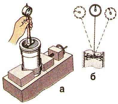
Scheme for measuring the inner diameter of the cylinder liner is shown in fig. 2.
Coolant circulates between the walls of the cylinder block and the liners.
The end walls and transverse partitions of the cylinder block in the lower part have tides designed to form the upper supports of the crankshaft.
These bosses are fitted with covers that serve as lower crankshaft bearings.
The bosses, together with the covers, form beds for the main bearings.
The beds for the main bearing shells are bored together with the main bearing caps, so the caps cannot be interchanged.
The cylinder block has a longitudinal channel, from which oil flows through the transverse channels to the crankshaft main bearings and camshaft bearings.
The cylinder block in the second and fourth upper bearings of the crankshaft has nozzles that serve to cool the pistons with a jet of oil.
On the outer surfaces of the cylinder block there are machined mating surfaces for mounting a centrifugal oil filter, a liquid pump, a fine fuel filter, an oil filler neck
The flatness of the upper surface of the cylinder block must not exceed 0.15 mm (0.05 mm for a new block).

The diameter of the holes in the cylinder block for the main bearing shells when tightening the cap bolts with a torque of 190-210 Nm should be 81 + 0.022 mm.
When the surfaces of the main bearings are worn up to a diameter of more than 81.03 mm, it is recommended to restore the bushing to a larger outer diameter.
Inverting and rearranging the main bearing caps is not allowed.
The surface roughness of the holes for the main bearing shells should be Ra≤0.63 µm.
The difference between the depths of the bores for the cylinder liner shoulder should not exceed 0.04 mm.
Oil channel openings must be free of dirt.
The cavity of the cylinder block, washed by the coolant, and the oil channels must be checked for leaks with water at a pressure of at least 0.4 MPa for 1 minute.
Coating of raw surfaces should be done with a primer.
When pressing the front, middle and rear bushings of the camshaft, the oil holes in the bushing and block must match.
The rear camshaft bushing must be pressed into the block to a depth of 7 mm relative to the rear plane, and the front bushing should be flush with the front plane of the block.
The bushings must be pressed in using a set of special mandrels (Fig. 3).

The deviation from the flatness of the mating surface of the oil sump should not exceed 0.25 mm.
When testing the oil sump with a liquid under a pressure of at least 0.1 MPa, no leaks or drops appear over the entire surface.
The deviation from the flatness of the surfaces "A" and (Fig. 4) of the front support of the diesel engine should not exceed 0.1 mm.
The deviation from the parallelism of the surfaces "B" relative to surface "A" should not exceed 0.2 mm over a length of 100 mm.
Surfaces "B" must lie in the same plane;
The riveted part of the limiter should not protrude above the plane of the shock absorber plate by more than 0.5 mm.
The shock absorber rubber should not have cracks or tears.
When the shock absorber is compressed with a force of 2 kN, its deformation in height should be 2.5 ± 0.5 mm.
Mounting interfaces of body parts

")
")
")
")
")
")