The VAZ-2123 engine is equipped with a distributed phased fuel injection system: gasoline is supplied by injectors to each cylinder in turn in accordance with the engine operation order
The electronic engine control system (ECM) consists of a controller, sensors for engine and vehicle operation parameters, as well as actuators.
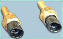
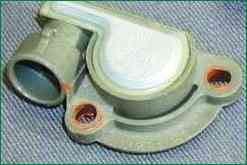
The coolant temperature sensor is a thermistor (resistor whose resistance changes with temperature).
The sensor is wrapped in the coolant outlet on the cylinder head.
At low temperature, the sensor has a high resistance (at -40°C - 100 kOhm), and at high temperature - low (at 100°C - 177 Ohm).
The controller calculates the coolant temperature from the voltage drop across the sensor.
Voltage drop is high when the engine is cold and low when the engine is warm.
Coolant temperature affects most of the characteristics controlled by the controller.
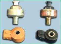
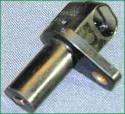
A knock sensor is attached to the top of the cylinder block and detects abnormal vibrations (knock) in the engine.
The sensitive element of the sensor is a piezoelectric plate.
During detonation, voltage pulses are generated at the output of the sensor, which increase with increasing intensity of detonation impacts.
The controller, based on the sensor signal, regulates the ignition timing to eliminate detonation fuel flashes.
The mass air flow sensor is located between the air filter and the left side of the air inlet.
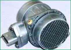
It contains temperature sensors and a heating resistor.
The passing air cools one of the sensors, and the sensor electronics convert this temperature difference into an output signal for the electronic control unit.
Two types of mass air flow sensors can be used in different variants of fuel injection systems.
They differ in the device and in the nature of the output signal, which can be frequency or analog.
In the first case, depending on the air flow, the signal frequency changes, and in the second case, the voltage.
The ECU uses information from the mass air flow sensor to determine the duration of the injector opening pulse.
The
Speed sensor of the vehicle is mounted on the transfer case between the speedometer drive and the tip of the speedometer drive flexible shaft.
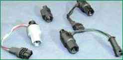
The principle of operation of the sensor is based on the Hall effect.
The sensor outputs rectangular voltage pulses to the controller with a frequency proportional to the speed of rotation of the drive wheels.
The throttle position sensor is mounted on the side of the throttle assembly and connected to the throttle shaft.
The sensor is a potentiometer, one end of which is supplied with a plus supply voltage (5 V), and the other end is connected to ground.
The third output of the potentiometer (from the slider) is the output signal to the controller.
When the throttle valve is turned (from the action on the control pedal), the voltage at the output of the sensor changes.
It is below 0.7V when throttle is closed.
When the damper opens, the voltage at the sensor output rises and should be more than 4 V when the damper is fully open.
By monitoring the output voltage of the sensor, the controller adjusts the fuel supply depending on the throttle opening angle (i.e. at the request of the driver).
The throttle position sensor does not require any adjustment as the controller senses idling (t.e. full throttle closing) as the zero mark.
Crankshaft position sensor - inductive type, designed to synchronize the controller with the top dead center of the pistons of the 1st and 4th cylinders and the angular position of the crankshaft.
The sensor is installed on the cover of the timing gear drive opposite the setting disk on the crankshaft pulley.
The driving disk is a gear wheel with 58 equally spaced (6°) cavities.
At this step, 60 teeth are placed on the disk, but two teeth are cut off to create a synchronization pulse (the "reference" pulse), which is necessary to coordinate the operation of the controller with the TDC of the pistons in the 1st and 4th cylinders.
As the crankshaft rotates, the teeth change the sensor's magnetic field, inducing AC voltage pulses. The installation gap between the sensor core and the disc tooth must be within (1 ± 0.2) mm.
The controller determines the crankshaft speed using the sensor signals and sends pulses to the injectors.
An oxygen concentration sensor (lambda probe) is installed on the exhaust pipe of the exhaust system.
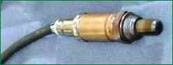
The oxygen contained in the exhaust gases reacts with the oxygen sensor, creating a potential difference at the output of the sensor.
It varies from approximately 0.1 V (high oxygen - lean mixture) to 0.9 V (low oxygen - rich mixture)
For normal operation, the sensor must have a temperature of at least 360°C.
Therefore, for quick warm-up after starting the engine, a heating element is built into the sensor.
By monitoring the output voltage of the oxygen concentration sensor, the controller determines which command to adjust the composition of the working mixture to apply to the injectors.
If the mixture is lean (low potential difference at the sensor output), then a command is given to enrich the mixture.
If the mixture is rich (high potential difference), a command is given to lean the mixture.
")
")
")
")
")
")